So Coris,
This power supply upgrade seems interesting.
Your design seems very sophisticated and interesting.
To implement a version of your power supply, I had already upgrades to 2700uf low esr caps.
I wonder if I upgraded these to the 5f and 3f values but installed an additional relay to short the caps to ground at turn off... triggered by the same circuit that mutes the outputs.
It does not have the visual led reference or the re settable triggers or the new voltage regulators, but I wonder if this would get some way to the quality of your design.
great work as usual.
Hi PhopsonNY
First I want to advise about some aspects for everybody who may want to experiment with such capacities on AVCC-VddL/R of ES9018 (or whatsoever device).
The huge energy these caps can store, it may be dangerous if one do not take some precautions. A short heaving these caps as power source it mean a 10A or more. Such currents just blow up and burn everything in its way.
The original regulators on 105/105D, and even 95 it support the rush in currents, and work well with such caps at their outputs. But, the most important here is to isolate the DAC chip from the original power rails on AVCC and VddL/R, before doing any experiment which involve these regulators. If it happen something wrong and the regulators fail to keep the right tensions, then the DAC chip may be damaged. The AVCC is 4v tolerant by the book, but VddL/R it have to be exactly 1,2v...
So, isolate the chip from these power rails, mount these Farad caps in right places, and observe the regulators to have the right tensions on the outputs. Use some loads to verify that they are working well. Then and only then, if everything is safe, connect the DAC chip to these power rails.
When using such capacities, there is a must to have a (fast enough) discharge circuit connected at once the system is powered off. Please take into consideration to correlate the current capabilities of the relays to the discharge circuits. The relays contacts can easily be welded if to high currents, and then the low impedance of the discharge circuit can be at the regulators outputs...
I do not think the Mute signal used by the output relays it may be the right one to control the discharge relays and its circuits.
For such control the best way is to use a power line which is up at once you press the power button, and goes down at once the player is turned off. I will suggest to be used the power line (15v ) which activate the analogue power relay. Another power line it may be that used for USB ports of the device.
Please have in mind that the quite slow ramp of the AVCC and VddL/R, when using such powering way, it produce some spikes, which are audible on outputs, if the amp is already up and connected while power up sequence. So connect or start up your amp/preamp after a safe delay of time.
It is right that there is no any LED on my Sabre PSU, and this is intentional.
I think there is no any clue to have a LED device on AVCC or on core analogue rail of the DAC chip. Such components are noisy, and completely unnecessary for this purpose.
The more important is to have a visual reference for the discharge event, so the user could get the information about when it may be allowed to turn on again the player.
My board it provide a port for connecting an external signalizing device for the discharge process. At least, one more miniature bulb is the right thing to connect to this port, as this it accelerate the discharging process.
There is no any clue to use LED devices for such visualizing, as a LED do nothing under 1,4, or 1,2v...
Last edited:
Coris, Phopson -
Can your power supply mods be implemented in a BDP 95?
Yes, of course., as it use a similar power system for DAC chip.
Hi Joe
May I address to you my post here...
I think I came up on a firmware issue on 105 model (I have updated to the last one). As this issue it is not revealed for the common user of the player, it seems that Oppo it may not be known with and/or could not address it.
My intention is to have your opinion or a confirmation about, as you are also an very experienced "user"")
As you know I also configured the DAC of my 105 for 2+2 channel (stereo) output. Just wonderful sound, as you already experienced.
I have tested in the last time the USB IN. The sound quality is even better than the rest of the inputs/sources. Well, I have switched off the player with the last selected source: USB IN.
After power on I observed that one channel is much louder, than another one. No any distortion in sound, just a mismatch with the volumes/balance. Switching back and forth the sources, the balance become normal for USB IN.
I suspect that when the device is power cycled with the source USB IN selected, for one or another reason the DAC it get a wrong information about the channels polarity to be used for outputs. When in 2+2 configuration, one of these pairs it get somehow (too much) in phase, while the another pair it may be out of phase, or it is set it up in opposite phase. Well, something wrong it happen and the DAC chip registries are set it up wrong, while power cycling occur. Refreshing the Sources after power on, it solve this quite clear firmware issue. Is seems that the normal use of the DAC chip (designed channel configuration), may not reveal this firmware bug.
By the way, this issue is particular to USB IN selected source.
Have you (somebody else) experienced the same?
May I address to you my post here...
I think I came up on a firmware issue on 105 model (I have updated to the last one). As this issue it is not revealed for the common user of the player, it seems that Oppo it may not be known with and/or could not address it.
My intention is to have your opinion or a confirmation about, as you are also an very experienced "user"
As you know I also configured the DAC of my 105 for 2+2 channel (stereo) output. Just wonderful sound, as you already experienced.
I have tested in the last time the USB IN. The sound quality is even better than the rest of the inputs/sources. Well, I have switched off the player with the last selected source: USB IN.
After power on I observed that one channel is much louder, than another one. No any distortion in sound, just a mismatch with the volumes/balance. Switching back and forth the sources, the balance become normal for USB IN.
I suspect that when the device is power cycled with the source USB IN selected, for one or another reason the DAC it get a wrong information about the channels polarity to be used for outputs. When in 2+2 configuration, one of these pairs it get somehow (too much) in phase, while the another pair it may be out of phase, or it is set it up in opposite phase. Well, something wrong it happen and the DAC chip registries are set it up wrong, while power cycling occur. Refreshing the Sources after power on, it solve this quite clear firmware issue. Is seems that the normal use of the DAC chip (designed channel configuration), may not reveal this firmware bug.
By the way, this issue is particular to USB IN selected source.
Have you (somebody else) experienced the same?
Last edited:
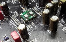
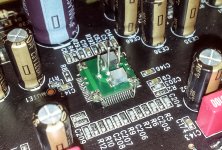
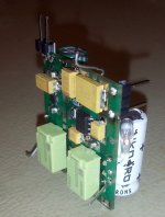
First step in my Analogue Power mod for ES9018 (a more professional approach...).
The small 4 layer PCB it help to connect the chip`s lifted pins to AVCC and VddL/R connections points, as to the AGND. The board is glued on the chip and its bottom GND plane it is also a shield for the new power connections. So, the analogue pins it can be connected further to a different/customized power system.
As you may guess, I will connect to it my large capacities PSU...
Attachments
Last edited:
Member
Joined 2009
Paid Member
Hi Coris,
It would be a great service if you could edit your first post (only the OP has this option) and provide a little summary of the mods catered to in this thread in the order which provides the most benefit.
For me, I want the best multi-channel sound so not all these mods are relevant to me, but I would think for others new to this thread a summary at the start would be great.
Hi Bigun
Thanks for suggestion. I will take a look...
BTW, the multichannel stage it can be also improved. These mods are about the DAC and post DAC processing, so it apply to the multichannel too. What you see in my last pictures is actually a modification on the multichannel board...
Thanks for suggestion. I will take a look...
BTW, the multichannel stage it can be also improved. These mods are about the DAC and post DAC processing, so it apply to the multichannel too. What you see in my last pictures is actually a modification on the multichannel board...
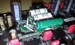
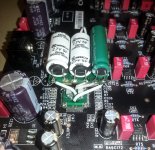
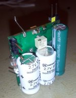
Here is the complete modification/implementation of the Sabre Analogue PSU.
This modification is done on the multichannel board of a 105v model.
I used this time a 6F cap for VddL/R - 1,2v. Silver wires connections, no longer than 15mm. The final version (a little bit smaller) of the PSU board (populated) is also to be seen here.
This modification is done on the multichannel board of a 105v model.
I used this time a 6F cap for VddL/R - 1,2v. Silver wires connections, no longer than 15mm. The final version (a little bit smaller) of the PSU board (populated) is also to be seen here.
Attachments
Last edited:
The original regulators on 105/105D, and even 95 it support the rush in currents...,
Hi Coris
It is important to understand that the regulator with inbuilt protection will react initially as current sources until the large value cap nears the regulator's voltage where it will change from 'current send mode' to voltage regulator. It does this by nature, not by design. The only question, if that be the case, is the delay and if the circuits and possibly the attendant logic circuits don't sputter because it expects things turning 'on' in a matter of a second or less. The rate of the current send and the cap has in effect a time constant, a delay.
Think of the cap with its large value, acting as a kind of electronic "flywheel" that will resist change down to a frequency below 1 Hertz, this I believe is the key to what it does (and why it is sonically heard as a positive) because any disturbance at low frequencies also tends to have a large amplitude, known as frequency versus amplitude f/2 factor.
The other key to what it does is that PDM and delta-sigma DACs only have two states, one low (ground) and one high (rail) and the latter, assuming ground is reasonably clean, means that the 'on' state is really clipping the rail. This means that any aberration on the rail has a direct in path in and any noise, any sagging, any modulation (like switching) is now basically turned into jitter. I am not the only one who has drawn this conclusion, so has Ted Smith, the designer of the PS Audio 'Direct Stream' - in his case he has a filter (I am fairly sure it is passive) that filters anything above 1 Hertz (probably 3rd order?) - but extreme packed electrons/flywheel/extreme cap, will work it's magic even below 1 Hertz.
And then when you add the post-DAC filter (the controversial Rasmussen Effect as named by Ken Newton), those two in tandem makes a significant improvement to any delta-sigma DAC, now that conclusion has been based on results derived from a number of DACs of different brands, and thoroughly blind tested.
All of the above, including SAW clocking, is now in the public domain. All I ask is perhaps some will give me some due credit, nothing more. Right now, an inexpensive USB DAC is being developed here in Australia by Claytronics Australia, it will be incorporating the above and Clay will indeed only owe me by simply giving me credit and I believe he is a gentleman of his word. But gradually these techniques will be adopted commercially as Clay is now just the first.
Cheers, Joe
Hi Joe,
Wow what can I say - I was already very happy with my new PCM1794 Amanero USB Dac & then yesterday I performed two mods as per Joe's suggestion.
Dac psu pins decoupling supercap mod plus the "Rasmussen Effect" post Dac filter mod.
I was absolutely gob smacked & the sound improvements.
The bass was already good but now has real weight & more impact.
Soundstage is wider & higher with no loss of detail even tho is is now about -1.3 db at 20k
So yes - thank you very much Joe for sharing this with us
Cheers
Clay
Here is the complete modification/implementation of the Sabre Analogue PSU.
This modification is done on the multichannel board of a 105v model.
I used this time a 6F cap for VddL/R - 1,2v. Silver wires connections, no longer than 15mm. The final version (a little bit smaller) of the PSU board (populated) is also to be seen here.
Hi Coris,
I have always admired your wiliness to experiment and to share the findings with DIY community. Just a friendly tip: don't ever lose the notion on how to achieve really great results - learning the widely accepted, documented and validated electronic design rules, supported with soon to follow empirical testing (to prove the theory and possibly trickle your creativity, and add to the knowledge base).
There are simple rules when it comes to the digital electronics - lower the ground plane noise first & isolate the high frequency switching devices from analog circuitry. Next, make sure the power supply rail noise has sufficient paths of exact specifications (at least for the given noise environment) to find its way to that low noise ground plane. In general, paths have to ensure very low impedance for a wide frequency range spectrum, some would say (this is highly debatable topic) into a gigahertz range - and would go to the extents of an RF principle where everything is buried into the ground plane to achieve the No1 rule in electronics - low noise.
Your latest set of upgrade suggestions and photos can give many people the wrong indicative. They are installed in a way that will prevent them from ever achieving the goal of a low noise environment. They also contain parts that are incapable of doing what they should to bring the power supply rail noise (very) close to the ground plane noise.
Nick
Hi Nick
Thanks for appreciations and advices. BTW, most of my modifications refer to the analogue stage of the device, and its power system. I know some of the rules you listed here, but all these refer to electronic design when about starting from scratch.
The point here in this BDP105 thread is to (try to) modify an already designed device so to get more out of it. These solutions presented here (not only by me) it may not be exactly by the book or by the "rules", but it bring improvements. These findings about improvements are based on quite much experimenting, faults and correcting the faults processes.
If I should design a DAC system and apply some of the approaches presented here, I will do it of course in another way, than trying to adapt some modules to an existent device.
My approach using these modules, is based on an appreciation that it is however better to have a compact and modular modification, than adding some components and connecting it by long wires, or many other improvisations (as you may also see in my previously experiments presented here).
To conclude, I would like to ask a question. How you (or other sceptics) may explain, that in spite of so many "broken rules", wrong approaches, and fully unprofessional way of doing, when applying these mods, there is improvement on the original device performances?
Well, you or others may not believe in such statements about improvements. There is OK. But then I have a very simple advice: try it yourself.
And maybe another advice just to finish: Do you or somebody else, have a better way to do it, or better practical ideas for the improvements this thread refer to, you are welcome to show/present it in fact.
Last edited:
Just a friendly tip: don't ever lose the notion on how to achieve really great results - learning the widely accepted, documented and validated electronic design rules, supported with soon to follow empirical testing (to prove the theory and possibly trickle your creativity, and add to the knowledge base)...
And who is guilty of what you are saying? Nobody that I see here.
Sometimes science (and I speak as somebody who know a number of scientists as friends for decades and all have been very supportive because they have recognised in me a talent to see beyond the obvious and they have treated me, a non-scientist, as an equal when it comes to these matters) have an innate conservativeness that is required as it places an important discipline upon them, one that must be adhered to. Many laud the 'scientific method' without actually understanding what it is and it is not as it is often portrayed - and that seems to be the gist I get from you, that you are presenting the popular understanding of what the 'scientific method' is. Example: Google Barry Marshall and Robin Warren.
Nothing that I have done has ever opened me up to the accusation of violating the principles of the 'scientific method'.
Misconceptions abound and have become populist and often just plain wrong - but very common.
Misconceptions about science - source Berkely: Tips and strategies for teaching the nature and process of science
MISCONCEPTION: There is a single Scientific Method that all scientists follow.
CORRECTION: "The Scientific Method" is often taught in science courses as a simple way to understand the basics of scientific testing. In fact, the Scientific Method represents how scientists usually write up the results of their studies (and how a few investigations are actually done), but it is a grossly oversimplified representation of how scientists generally build knowledge. The process of science is exciting, complex, and unpredictable. It involves many different people, engaged in many different activities, in many different orders. To review a more accurate representation of the process of science, explore our flowchart.
Niels Bohr has been quoted about physics and science "is not about understanding how things work, but what we can say about nature."
Science and physics (which includes electronics) is about observation and what we can say - and not having any total understanding of everything - in fact science and hence the scientific method is inherently unpredictable and not a cosy comfort blanket to retreat into.
So what is the 'scientific method' then - the act of collecting facts and knowledge.
Cheers, Joe
PS: When I pointed out a certain observation to a research scientist a few months ago, she told me that "people like you discover these things and then we scientists then have to figure it out." As far as she was concerned, the 'scientific method' includes non-scientists (as the above Berkeley quote notes that fact). When I pointed out to her that I had been accused of throwing out a perfectly good good hypothesis, she laughed and said the whole point of a hypothesis was that it should be questioned. So I will continue to challenge sacred cows. In real science, it is the brave that ends up contributing the most. Google Barry Marshal and Robin Warren on solving the riddle of stomach ulcers as being bacterial infections and treatable with antibiotics - ridiculed for years and ended up getting the Nobel Prize.
Last edited:
I was referring to a specific system (ground plane), with clearly established boundary of interest - the noise, its influence in digital sound reproduction, and proven techniques to correctly combat the issue, that are widely accepted, documented, validated and used in electronic industry. Based on my experiments, measurements, listening test and current set of techniques I use to decouple the power supply rails, they work 100% with great results.
Coris' "teaching" is in stark contradiction, compared to common, widely accepted and used techniques. They are also in contradiction to what I use to combat ground plane noise and decouple power supply rails. Now, the really weird thing is: I know you agree with me as well, when it comes to what I wrote in the rest of my post (you managed not to include), related to the power supply decoupling principles, and what works and what does not. You'd have to - otherwise you'll be doing very lousy job for your customers...
You pretty much used one sentence from my post to fuel you ego and prove something to yourself by going completely off tangent (and out of the boundary of interest that I firmly established in my initial post). This is fine as long as you are aware that I am okay with that, I forgive you, understand what you did, and at the same time don’t feel enlightened in any way - after I read your post.
Nick
ego...
Wow, this is all about ego now?
I decouple always too the power rails. What is the problem?
You can see the film decoupling caps soldered right on the DAC power pins (Oppo designers could`n do it so). I decouple the power rails with some very large capacity caps. It is this a problem? BTW, such caps it can be in the same time, decoupling, filtering or a very clean instant power source by itself... The overall paths for connecting these cpas, the GND, and the adjacent ultra low noise PSU are shorter than in the original board design.
I can hardly see your problem...
I also notice an interesting aspect about these (your) "observations" concerning this mod approach..
I have previously published and described about this very large decoupling capacities used for DAC chip as about a dedicated PSU, and experiments in the same field. There are to be seen there in my previous pictures, connections, wires and improvisations. Even though that enough disorder and improvisations, the improvements in sound quality were/is a fact. Well, no any negative comments about "electronic design rules" in that connection.
I have put order in all that mess, designed (by the rules...) some modules to improve even more this modification approach, its implementation, making it safer and increasing its quality, for a even better result. Now it come the "broken basic rules" comments, referring to this final improved mod quality... Is`n it strange?
Last edited:
Extreme_Boky said:
'Your latest set of upgrade suggestions and photos can give many people the wrong indicative. They are installed in a way that will prevent them from ever achieving the goal of a low noise environment. They also contain parts that are incapable of doing what they should to bring the power supply rail noise (very) close to the ground plane noise.'
Given that an existing design is being modified PLEASE be specific: what exactly has Coris done wrong?
It is incumbent on you (your duty) to state how he should have done it 'correctly.'
Thanks in advance.
Given that an existing design is being modified PLEASE be specific: what exactly has Coris done wrong?
NOTHING!
In fact I am doing exactly the same thing.
So is Clay - and he is bringing out a commercial product that I believe will shortly be sold by Southport Hi-Fi, and that may be only the beginning.
This is good news that is being slagged from certain individuals, we should be celebrating what is being done. At Soutport Hi-Fi GTG on Saturday, many turned up, some from as far as Melbourne, and they all heard it for the first time and revelled in it. Remember, this is an Oppo 105D with an ES9018 Sabre DAC and that many there said they had not heard a Sabre DAC implementation they had liked, but this was different. One was Bill Hobba and he said this was not a Sabre DAC sound any more and then turned to me and said "this is a no-brainer Joe, when can you get me one, sooner the better."
It is incumbent on you (your duty) to state how he should have done it 'correctly.'
Good point.
But remember he is the one who brought the 'ego' factor - somehow we are not allowed to be enthusiastic and passionate about what we have acheieved. Why? That's a good question.
Nick I believe, is in Sydney and like all audiophiles is welcome to come here and I don't bear grudges, but it gets a little tiresome at times. Let's be doers and let's be creative, not negative, and finally be forgiving.
Come along Nick, you will be heartily welcome.
Cheers, Joe
Last edited:
- Home
- Source & Line
- Digital Source
- Oppo's BDP105 - discussions, upgrading, mods...