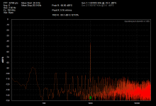
OK so here is the symptom. Measurements with the QA400 distortion analyzer and QA190 differential probe clamped via alligator clips on the speaker cables.
These are the distortion results at 48KHz sampling rate:
16K: 0%
8K : 0.019%
4K : 0.026%
2K : 0.014%
1K : 0.05% -- AND WHEN SIGNAL IS REMOVED THERE IS AN ECHO OF THE 1kHz SIGNAL!!!
What I mean by echo is that the QA400 applies a test tone to the unit in short bursts. The echo is that of the test tone burst starting and stopping, and eventually fading away.
The cap bank is 88,000uF per polarity per channel, arrange as CRC with R=0.1 Ohm.
I have installed 330uF caps on the output boards Cx positions, thinking PS bypass. Can this be causing the issue?
Another issue *may* be the large ground wire loop from PS to FE and back along the output board ground traces. B
Any help here would be most appreciated.
Into a speaker, that's why I can hear the echo. The quantasylum folks say that the echo is a function of the unit, not of the DUT.
The point to purchasing the QA400 was to be able to visually adjust P3, as at the time, I had no scope. The scope that I bought is being sent back as it is not functional. So, no P3 twirling for a while yet.
It sounds less and less aggressive as it warms up. The thermistors are bent over and touching the washers that are holding the transistors to the heatsink.
I will test dazed2's F5 and retest my F5T for THD at the same dbFS, once I figure out what is going on with the noise measurements. Details of that are in the QA400 thread.
Can you see an FFT of the test from the QA400? If so, you can set P3 with that. P3 will have huge effects on the size of the 2nd harmonic spike Vs. the 3rd harmonic spike.
Setting P3 by looking at the distortion residual, you need more than the scope -- you must have the distortion analyzer. The scope is just the screen.
Setting P3 by looking at the distortion residual, you need more than the scope -- you must have the distortion analyzer. The scope is just the screen.
F5T THD and F5.... the F5 sounds more aggressive and punchier. The speakers used on the THD test is a small KOSS, just to be consistent. pic on the left is the turbo.
Just starting to learn how to use the QA400. I exported the F5Turbo data (but not the F5) The second harmonic is 14dB higher than the 3rd harmonic.
Just starting to learn how to use the QA400. I exported the F5Turbo data (but not the F5) The second harmonic is 14dB higher than the 3rd harmonic.
Attachments
Last edited:
Yes, I am hoping that these are induced from the cheap open frame transformer I used for the auxilliary circuits. A shielded and potted one is on order from SumR.
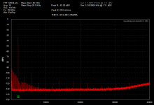
I did another try with a resistor ladder on the output instead of using the differential probe. Also changed was a BNC to RCA connection. Instead, I used a delco quadstar cable and modified a BNC terminator to fit one end and soldered an RCA on the other. It produced the attached graph.
I did another try with a resistor ladder on the output instead of using the differential probe. Also changed was a BNC to RCA connection. Instead, I used a delco quadstar cable and modified a BNC terminator to fit one end and soldered an RCA on the other. It produced the attached graph.
Attachments
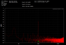
A lot of the noise is the mains and it's harmonics. I can see a broad band around 60Hz.
I can count all the harmonics from 180Hz, 300Hz through passed 900Hz and continuing up past 3kHz.
You have to find the cause of these odd harmonics and attenuate them.
Where are the harmonics coming from?
From the two graphs that BigE showed, one of them is his F5 Turbo, which he has a smaller EI core transformer running the soft start and slow charge. I don't think it is the cause of the 60Hz harmonics.
The second graph is actually my F5, which also shows the similar harmonics! This build does not have soft start nor slow charge circuit. Power is fed via a toroid, and just CRC filtering.
Could it really be ringing from the diode bridge? I thought that noise was much higher frequencies?
Or would it be from Loop Area RF? although Looking at BigE's cleaned up build every wire seems to be heavily twisted, although still using PCB for caps etc.
Last edited:
The harmonics are coming from the switching of the mains waveform and from the distortion on the mains waveform.
The PSU's job is to attenuate these harmonics until they don't interfere with the operation of the equipment.
There could be a wiring fault in the test apparatus, or a wiring fault in the DUT, or just a very badly assembled PSU without effective filtering.
The first place I would look is the PSU. That is the easiest to fault find and correct.
Then simplify the DUT to one channel and no ancilliaries, to enable fault finding in there and correct.
Finally looking at the test apparatus. This is very sensitive to wiring errors judging by comments made by others.
A couple of Members report that balanced impedance test leads MUST be used to get good resolution in the results.
Last edited:
Redux on SA/1 Amps
Hi All,
Back in Mid-July I posted an update to my SA/1 clones with the intent of using the chassis components and Power supply part being removed to be used in a F5T build. After waiting months for the caps and getting larger heatsinks and having everything black anodized, I have the amps back together.
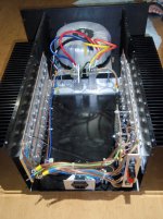
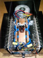
You can see the old pics on page 344 post #3425. The first new pic shows the relocated rectifiers. As Itsmee pointed out they were feeding heat into the caps, now they are on 1 inch square bar pedistals to raise them up so the leads to the caps can be short and as a heat sink attach to a heat spreader on the bottom of the chassis.With the increased bias current they now run around 36C.
AudioSan pointed out the heatsinks were too small. With the sinks at 50C and the transistor cases at 55C I could only run 4.6A of bias, should have been 5A, with the 48v supply voltage, or 220w. Just changing to the new larger sinks dropped the temp to 38C on the sinks. I was able to up the bias current to 6.8A or 312w with the sinks pushing 52C and the transistor cases at 54C.
The second pic shows the new CLC bank. Took out 118000uf and put in 568000uf with 3mh inductor in the middle of each rail. Loaded voltage is now 46v.
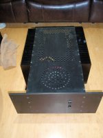
The third pic is just the top cover plate laid in place with all the holes I hand drilled and counter sunk before andonizing. The amp actually runs cooler with the top plate screwed in place, acting as another heat sink.
The next project will have to be adding a 500 square foot addition to my house for a sound room before I can build anymore equipment. Wife's orders.")
Thanks for all the comments that lead to the improvements.
Have a good one,
John
Hi All,
Back in Mid-July I posted an update to my SA/1 clones with the intent of using the chassis components and Power supply part being removed to be used in a F5T build. After waiting months for the caps and getting larger heatsinks and having everything black anodized, I have the amps back together.
You can see the old pics on page 344 post #3425. The first new pic shows the relocated rectifiers. As Itsmee pointed out they were feeding heat into the caps, now they are on 1 inch square bar pedistals to raise them up so the leads to the caps can be short and as a heat sink attach to a heat spreader on the bottom of the chassis.With the increased bias current they now run around 36C.
AudioSan pointed out the heatsinks were too small. With the sinks at 50C and the transistor cases at 55C I could only run 4.6A of bias, should have been 5A, with the 48v supply voltage, or 220w. Just changing to the new larger sinks dropped the temp to 38C on the sinks. I was able to up the bias current to 6.8A or 312w with the sinks pushing 52C and the transistor cases at 54C.
The second pic shows the new CLC bank. Took out 118000uf and put in 568000uf with 3mh inductor in the middle of each rail. Loaded voltage is now 46v.
The third pic is just the top cover plate laid in place with all the holes I hand drilled and counter sunk before andonizing. The amp actually runs cooler with the top plate screwed in place, acting as another heat sink.
The next project will have to be adding a 500 square foot addition to my house for a sound room before I can build anymore equipment. Wife's orders.
Thanks for all the comments that lead to the improvements.
Have a good one,
John
Attachments
Hi All,
The third pic is just the top cover plate laid in place with all the holes I hand drilled and counter sunk before andonizing.
Have a good one,
John
Did you use a pattern to drill all those cooling holes in the cover?
nash
The harmonics are coming from the switching of the mains waveform and from the distortion on the mains waveform.
The PSU's job is to attenuate these harmonics until they don't interfere with the operation of the equipment.
There could be a wiring fault in the test apparatus, or a wiring fault in the DUT, or just a very badly assembled PSU without effective filtering.
The first place I would look is the PSU. That is the easiest to fault find and correct.
Then simplify the DUT to one channel and no ancilliaries, to enable fault finding in there and correct.
Finally looking at the test apparatus. This is very sensitive to wiring errors judging by comments made by others.
A couple of Members report that balanced impedance test leads MUST be used to get good resolution in the results.
My first go at this is with the aux transformer. However, other devices also exhibit this behaviour, so it appears that the issue is with the set up of the test apparatus, and not the PSU.
I suppose changing to CLC would guarantee that the higher order harmonics are quenched.... I will give a pic of the Salas DCB1, with full regulation. It too shows harmonics.
Last edited:
Hi nashbap,
To drill a consistant pattern I taped graph paper to the top of the panel and used a spring loaded center punch to get the marks on one cover so the drill bit would not wander. I then drilled the corner holes on the two covers, one for each amp, and bolted the plates together. I then drilled all the holes with a small diameter bit that would not wander from the center punch mark. After drilling all the pilot holes I than drilled with the final hole size bit. After unbolting the two plates I then eased each hole with a counter sink bit, both sides, to bevel the holes, it deburrs the holes and looks good too. A lot of work but it flows a lot of air and the inside of the amp stays as cool as the outside.
John
My first go at this is with the aux transformer. However, other devices also exhibit this behaviour, so it appears that the issue is with the set up of the test apparatus, and not the PSU.
I suppose changing to CLC would guarantee that the higher order harmonics are quenched.... I will give a pic of the Salas DCB1, with full regulation. It too shows harmonics.
I built a pair of FET amplifiers (using Renesas 2SJ162/2SK1058 Lateral FETS) about 125W/channel to bi-amp my B&W803D speakers.
I went with CLC filtering off the start as I have too many bad experiences with HF noise getting in to the sound path. (60kuF total with 250mH choke)
Also use single point isolated ground bar, including a bridge safety ground. Even when connected with the preamp and DAC, one has to put the ear within an inch of the speaker to hear any noise. I discovered that one must keep all wiring away from the transformer, unless they are potted and shielded with mu-metal, toroids can be nasty for magnetic induction into nearby wires and the system ground.
If you don't want (or no room) to use an choke, ESP sound has a suggestion to minimize power supply harmonics with just resistors. Use a single 100mOhm resistor on each power supply +/- rail (of appropriate power rating). According to that site, it substantially reduces higher order harmonics.
Another suggestion would be to try these rectifiers: Vishay VS-20ETF02FP-M3
These are ultrasoft recovery, made for very low noise. I also snubbed with a 100n ceramic capacitor. Overall, great sound with little or no noise. If you want a number, about -88dB SNR. (HP8903B Audio analyzer)
gr.
Last edited:
Thanks roger57, the 100 mOhm resistor oj each rail ( ie CRC ) was already in place. It is now a 50 mOhm.
I'm trying to source some erse 14 awg 4.5 mH coils ( C = 88,000uF/rail/channel ). Erse has 16 awg in stock, and says 500 watt rating. I'm running around 45 VDC at that point, so 500 watt means 11 A capacity. The amp is biased to less than 1/2 of that, so it seems that the 16 awg may just work... 14 awg are not in stock.
Any opinions on the AWG or value of 4.5 mH?
Thanks!
- Home
- Amplifiers
- Pass Labs
- F5 Turbo Builders Thread