Thanks AndrewT, I can benefit from this a great deal, as there is such a loop in my amp -- the power bus that travels from the cap bank to the FE board does so along the output boards, with each ground connected. This terminates at a single point on either side. A perfect antenna.
A loop can be a receiving aerial or a transmitting aerial or both.
Pass a varying current around a loop and the aerial transmits radiation.
Place a loop inside a varying field and the aerial receives radiation.
Eliminate the loop and you eliminate the radiation, a bit too simple but it is the part I need for this explanation.
Make a loop and you are in effect making a circuit that will emit and receive radiation.
Your three plates are circuits with Loops.
They pass large varying currents around the Loops.
They will emit radiation.
Every other loop inside your amplifier will pick up some of that radiation.
Low Loop Area is a simple topology to eliminate radiation interference.
You learn something new everyday! Thanks for the explanation.
So can the size of the conductor be calculated or estimated as to how big that radiating loop will be?
So instead of plates, use say 14ga solid core copper wire, I would still imagine it being a loop, but perhaps a smaller radiating area. and be less of an antenna ?
Last edited:
A loop can be a receiving aerial or a transmitting aerial or both.
Pass a varying current around a loop and the aerial transmits radiation.
Place a loop inside a varying field and the aerial receives radiation.
Eliminate the loop and you eliminate the radiation, a bit too simple but it is the part I need for this explanation.
Make a loop and you are in effect making a circuit that will emit and receive radiation.
Your three plates are circuits with Loops.
They pass large varying currents around the Loops.
They will emit radiation.
Every other loop inside your amplifier will pick up some of that radiation.
Low Loop Area is a simple topology to eliminate radiation interference.
Thanks for the follow up!
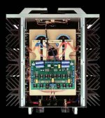
I'm really curius about how connecting plates would pick up aerial radiation more or less than a 12-14 ga wire running the same path. After your post I started looking at interior pics of amps. Pass Labs X350.5 uses connecting plates to connect 6 large caps together. What I'm doing is similar, except just 4 caps. Am I missing something? Here is a "naked" pic of the X350.5 for reference (some of the caps are under the top circuit board)

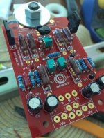
Working on the FE (front end) boards today. I know for most of you probably only a half hour or so to populate. I'm not as sure of myself. So I lay the parts all out as required for each board (2). I check each part against the BOM before inserting into the board. Banded resistors are checked with a meter. I adjusted the P3 pot to the center, as measured with a meter, before inserting.
To try and keep from having any cold joints I only insert a few items at a time, working from the center out. Then after soldering from the bottom I flip the board over and reflow from the top. For sensitive parts, like the nude resistors, I clip on a small copper alligator clip as a temp heatsink. Not sure this is all the best practice, but seems prudent and makes all the solder joints look consistent.
I tie wrapped the two JFETS (Q1-Q2) together because 6L6 and Dazed2 did. No one answered me why, but I did it anyway. Kind of like the old Heineken commercial making fun of people putting lemons in their Corona's😊
I kept all the smaller resistors off the board about an eighth. The 5 watt resistors are off the board about a quarter.
For soldering I'm using .032" 60/40 rosin core for small leads, .062" 60/40 rosin core for larger leads, both from Radio Shack. And just for information I'm using a Hakko FX-888 soldering station.
Anyway, here is a pic of one of the completed FE boards (don't make fun of my homemade board holder!)

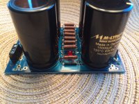
My 16 Mundorf 15,000uF 63v M-Lytic AG caps came in, so on to the Filter Cap boards
To try and keep from having any cold joints I only insert a few items at a time, working from the center out. Then after soldering from the bottom I flip the board over and reflow from the top. For sensitive parts, like the nude resistors, I clip on a small copper alligator clip as a temp heatsink. Not sure this is all the best practice, but seems prudent and makes all the solder joints look consistent.
I tie wrapped the two JFETS (Q1-Q2) together because 6L6 and Dazed2 did. No one answered me why, but I did it anyway. Kind of like the old Heineken commercial making fun of people putting lemons in their Corona's😊
I kept all the smaller resistors off the board about an eighth. The 5 watt resistors are off the board about a quarter.
For soldering I'm using .032" 60/40 rosin core for small leads, .062" 60/40 rosin core for larger leads, both from Radio Shack. And just for information I'm using a Hakko FX-888 soldering station.
Anyway, here is a pic of one of the completed FE boards (don't make fun of my homemade board holder!)

My 16 Mundorf 15,000uF 63v M-Lytic AG caps came in, so on to the Filter Cap boards
Thanks for the follow up!
I'm really curius about how connecting plates would pick up aerial radiation more or less than a 12-14 ga wire running the same path. After your post I started looking at interior pics of amps. Pass Labs X350.5 uses connecting plates to connect 6 large caps together. What I'm doing is similar, except just 4 caps. Am I missing something? Here is a "naked" pic of the X350.5 for reference (some of the caps are under the top circuit board)
View attachment 445417
I don't think you should put attention on just any comment on your build .... Keep going, looking good ...
I tie wrapped the two JFETS (Q1-Q2) together because 6L6 and Dazed2 did. No one answered me why, but I did it anyway.
Better thermal tracking of the devices, makes for more stable bias.
And, stay safe there ...
Lava Flow From Hawaii's Kilauea Volcano Reaches Pahoa Cemetery, Evacuations Possible - weather.com
Lava Flow From Hawaii's Kilauea Volcano Reaches Pahoa Cemetery, Evacuations Possible - weather.com
Thanks for all your comments and following my progress.
Honolulu, for those that don't know, is almost at the other end of the chain of the Hawaiian Islands. No chance of getting evaporated by lava, but our air quality suffers sometimes if the wind is blowing the right direction. They call it Vog (volcanic fog).
That makes sense, thanks for answering. Glad I like lime in my Corona��Better thermal tracking of the devices, makes for more stable bias.
I'm following your power supply build guide right now.
With the 4 82,000uF caps and the 8 15,000uF caps in each of my monoblocks, due I need the "optional" 3ea .47 resistors?
Last edited:
Dazed2, your up early! Or late night!Check that you installed the P1 and P2 correctly. If I'm not mistaken they should orient themselves opposite of each other.
So, i'm surprised you end up getting the 1240W not the 1260W. Did you have a hard time getting the legs into the holes?
Looks like one of the differences between the V2 and V3 boards. V2 they are reversed, V3 they are the same.
I guess I didn't pick the right model, the middle leg is just slightly offset, just took a little tweeking!
Dazed2, thanks for your keen eye on the pots. I have been following 6l6 build guides and it took me a couple views to understand the difference.Ahh my bad, didn't know they changed it in the V3 boards.
Re: the Jfets.
They are tied together so that they are the same temperature. Apparently otherwise bias drifts if the two see different temperature gradients.
I need extra eyes to keep away the magic smoke!
Almost complete with the first of the power supply boards. I didn't order the "optional" .47 ohm 3k resistors. Although no one answered me directly it seems with my higher voltage rails and larger cap bank, the more pathways for the power the better? Anyway, another order into Partsconnextion, and another overnight delivery and I can finish the second one. FYI, I'm using Mills 5k's
Due to space I split the board (also using monolithic bridges) one cap back will sit above the other.

Due to space I split the board (also using monolithic bridges) one cap back will sit above the other.

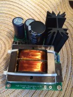
Besides the actual amp I need to build a control and fan circuit. To feed the 12vdc fan, power switch, soft start, slow charge, and overheating cutout I need a good 12vdc power supply.
K&K Audio has a new larger power supply, 1 amp, that should have plenty of power to run the fan and all the relay's. I received the boards and the parts and got those together also.

K&K Audio has a new larger power supply, 1 amp, that should have plenty of power to run the fan and all the relay's. I received the boards and the parts and got those together also.

I have a few PCB smoothing banks, very few.You learn something new everyday! Thanks for the explanation.
So can the size of the conductor be calculated or estimated as to how big that radiating loop will be?
So instead of plates, use say 14ga solid core copper wire, I would still imagine it being a loop, but perhaps a smaller radiating area. and be less of an antenna ?
I mostly use hard wired capacitors for smoothing the rectified DC.
I run a twisted pair from transformer to rectifier.
I run a twisted pair from rectifier to capacitor1.
I run a twisted pair from capacitor1 to capacitor2.
I run a twisted pair from capacitor2 to amplifier.
At every termination I try to minimise Loop Area.
I find this gives so little radiated interference that I can pass an unscreened interconnect anywhere around the PSU and the transformer, that I cannot measure (on a 200.0mVac DMM) any increase or change in output noise from the amplifier.
In my (somewhat blinkered) view a twisted pair hard wired PSU performs better than any pcb or plate version of the capacitor bank.
I am an absolute believer in twisted pairs.
Coast, put on your thinking cap instead of blindly following layouts that are conceived to make assembly cheaper. And look nice !Thanks for the follow up!
I'm really curius about how connecting plates would pick up aerial radiation more or less than a 12-14 ga wire running the same path. After your post I started looking at interior pics of amps. Pass Labs X350.5 uses connecting plates to connect 6 large caps together. What I'm doing is similar, except just 4 caps. Am I missing something? Here is a "naked" pic of the X350.5 for reference (some of the caps are under the top circuit board)
View attachment 445417
Think about LOOP AREAs for every changing current circuit.
It is thinking time that is not wasted. It applies to every circuit you assemble.
Non changing current, i.e. pure non varying DC, does not create EMI.
Everything else that varies, even pure undistorted sinewave, creates EMI from the Loops that it flows around.
Here you saw, you thought and you adopted.I tie wrapped the two JFETS (Q1-Q2) together because 6L6 and Dazed2 did. No one answered me why, but I did it anyway.
Pity you did not analyse why?
Last edited:
Andrew T. Thanks for following up on your previous comments. Following "blindly" is all I can do, as I have no real knowledge. So I try and ask questions and look at what others have done that are successful. But I have to admit that my eye looks to symmetry and neatness in what I build.
I'm interested in RF being picked up by the amp as Honolulu has a higher than normal amount of it. Some audio manufacturers have sent pre-production units to my friend here that owns a HIFI store to check, due to the known high rate.
In my build, these large caps are followed by 4ea 15,000uF caps, then 14ea .47ohm resistors, then another 4ea 15,000uF caps (per monoblock). If the plates did pick up any RF would not these additional caps and resistors clean it up?
In my build, these large caps are followed by 4ea 15,000uF caps, then 14ea .47ohm resistors, then another 4ea 15,000uF caps (per monoblock). If the plates did pick up any RF would not these additional caps and resistors clean it up?
No, its not the RF bleeding through the power supply that AndrewT is talking about its the RF that is radiated by the plates that can interfere with the amplifier.
- Status
- This old topic is closed. If you want to reopen this topic, contact a moderator using the "Report Post" button.
- Home
- Amplifiers
- Pass Labs
- Aloha F5 v3 Monoblock build