Hi just a guy,
Are there any advantages in using your method? Wouldn't it be easier just to simulate one of the actual intended modular units, and to then use the Multiple Speakers tool to determine the overall performance of the stacked-cabinet array? That way, the S2 limitation never becomes an issue, and it is not necessary to multiply the cross-sectional areas used in the simulation by the number of intended modular units.
Using either method though, the results should be identical.
Thanks. I won't make any changes to Hornresp until you confirm that the 'SPL + Phase' and 'Ze + Phase' exported text files, manually modified as previously outlined, work okay with your other software.
Kind regards,
David
I sim as a single horn with several drivers with the understanding (understood to me at least) that the intention is to chop that one horn up into several modular units.
Are there any advantages in using your method? Wouldn't it be easier just to simulate one of the actual intended modular units, and to then use the Multiple Speakers tool to determine the overall performance of the stacked-cabinet array? That way, the S2 limitation never becomes an issue, and it is not necessary to multiply the cross-sectional areas used in the simulation by the number of intended modular units.
Using either method though, the results should be identical.
I didn't get to check the utility of the .frd and .zma files last night, hopefully I can get into that after work today.
Thanks. I won't make any changes to Hornresp until you confirm that the 'SPL + Phase' and 'Ze + Phase' exported text files, manually modified as previously outlined, work okay with your other software.
Kind regards,
David
Hi just a guy,
Are there any advantages in using your method? Wouldn't it be easier just to simulate one of the actual intended modular units, and to then use the Multiple Speakers tool to determine the overall performance of the stacked-cabinet array?
How would I know the details of each intended modular unit without running it through Leach's math as a whole first?
Thanks. I won't make any changes to Hornresp until you confirm that the 'SPL + Phase' and 'Ze + Phase' exported text files, manually modified as previously outlined, work okay with your other software.
Kind regards,
David
This is the busy time of year and I'm completely swamped but I wanted to get some results so I did this quick experiment really fast.
First I chose a random Hornresp file and looked at the SPL and impedance graphs.
An externally hosted image should be here but it was not working when we last tested it.
Next I took the SPL + Phase from Hornresp, removed the header and renamed as .frd, took that .frd file and opened it in Jeff Bagby's Passive Crossover Designer (PCD). And I did the same to create the .zma file. I got this result.
An externally hosted image should be here but it was not working when we last tested it.
An externally hosted image should be here but it was not working when we last tested it.
So far so good, now I wanted to check phase. I took the .frd and .zma files and opened them in Bagby's Response Modeler. Then I extracted phase using Bagby's phase extraction tool and compared against the phase that Hornresp reported. (In the .zma file I showed Bagby's phase extraction tool, since it's right beside the .zma graph anyway.)
An externally hosted image should be here but it was not working when we last tested it.
An externally hosted image should be here but it was not working when we last tested it.
Hornresp phase on the left, Bagby's extracted phase on the right in each picture. The .zma phase is almost identical but the SPL phase isn't even close. If I wasn't half asleep I might be able to come up with a theory for why they are different but I can't really think right now. I will also run through these results later to confirm they are correct and I didn't mess anything up.
I was never really sure of what Hornresp was doing with corrected or wrapped phase; not sure which is applicable to any given situation. And fwiw, the phase window in Hornresp gives a result that is not similar to either the Hornresp SPL + phase or Bagby's extracted phase displayed in the post above.
.zma phase seems to be simple, but I have no idea what's going on with these 3 different versions of SPL phase.
.zma phase seems to be simple, but I have no idea what's going on with these 3 different versions of SPL phase.
I've got a couple more minutes to blab before work so...
I've never understood the definition of corrected phase in the Hornresp Help file but I just assumed it added delay based on group delay below tuning (indirectly because of the horn length). But I don't understand why the SPL + Phase txt chart gives a different response than the Phase window graph in Hornresp.
I assume Bagby's phase extraction process does not correct for group delay (horn length) into account and that's probably at least part of the reason why it's different. But the fact that the results are so dramatically different than Hornresp's leads me to believe there's something else going on too.
Some of Bagbey's software is great. Some of it is a little buggy.
Over the past few years I have coe across a couple of situations where it produced results that were a little out to lunch.
I stopped using it about a year ago. (Box modeler)
The crossover modeler is awesome.
A friend of mine who is a PHD in acoustics has come to similar conclusions. He worked with Jeff on his crossover modeler helping tweak it.
How would I know the details of each intended modular unit without running it through Leach's math as a whole first?
Hi just a guy,
If by "running it through Leach's math" you mean using the Hornresp 'System Design With Driver' tool to find an optimum hyperbolic-exponential horn design, then it should be applied to the intended modular unit, rather than to a single-horn equivalent of the final multiple-cabinet array. The overall response of the final system is likely to be a bit smoother that way.
Kind regards,
David
Hi just a guy,
Many thanks for carrying out the checks - it seems that the contents of the proposed .frd and .zma files will be correctly recognised by your other design software.
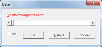
The SPL + Phase txt chart shows standard wrapped phase. To see standard wrapped phase in the Phase window graph in Hornresp, it is necessary to move the Delay slider to the far left-hand side (as shown in the attachment).
The difference is due to the horn length not being taken into account, as you guessed. There is nothing else going on, though.
Thanks again for your help - I will proceed with the implementation of the .frd and .zma file export options.
Kind regards,
David
Many thanks for carrying out the checks - it seems that the contents of the proposed .frd and .zma files will be correctly recognised by your other design software.
But I don't understand why the SPL + Phase txt chart gives a different response than the Phase window graph in Hornresp.
The SPL + Phase txt chart shows standard wrapped phase. To see standard wrapped phase in the Phase window graph in Hornresp, it is necessary to move the Delay slider to the far left-hand side (as shown in the attachment).
I assume Bagby's phase extraction process does not correct for group delay (horn length) into account and that's probably at least part of the reason why it's different. But the fact that the results are so dramatically different than Hornresp's leads me to believe there's something else going on too.
The difference is due to the horn length not being taken into account, as you guessed. There is nothing else going on, though.
Thanks again for your help - I will proceed with the implementation of the .frd and .zma file export options.
Kind regards,
David
Attachments
Hornresp Update 3620-141025
Hi Everyone,
CHANGE 1
The S2 upper limit for a hyperbolic-exponential horn has been increased to 999999.9 sq cm.
CHANGE 2
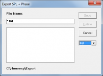
'SPL + Phase' data can now be exported as either a .txt or .frd (header excluded) file.
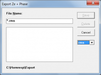
'Ze + Phase' data can now be exported as either a .txt or .zma (header excluded) file.
My thanks to Mårten and 'just a guy' for their help.
Kind regards,
David
Hi Everyone,
CHANGE 1
The S2 upper limit for a hyperbolic-exponential horn has been increased to 999999.9 sq cm.
CHANGE 2
'SPL + Phase' data can now be exported as either a .txt or .frd (header excluded) file.
'Ze + Phase' data can now be exported as either a .txt or .zma (header excluded) file.
My thanks to Mårten and 'just a guy' for their help.
Kind regards,
David
Attachments
Last edited:
Hi just a guy,
If by "running it through Leach's math" you mean using the Hornresp 'System Design With Driver' tool to find an optimum hyperbolic-exponential horn design, then it should be applied to the intended modular unit, rather than to a single-horn equivalent of the final multiple-cabinet array. The overall response of the final system is likely to be a bit smoother that way.
Kind regards,
David
Yes, I meant the System Design With Driver tool.
Ok, here's a quick experiment comparing your method to mine and using the same random Hornresp file as the last post. The requirement is a stack of eight modular horns that work as a single 32 hz horn in 2 pi space. Each modular horn should be 30 cu ft or less.
Disregard spl levels in the graphs, I forgot to change Eg for impedance load with each example and I'm not going to change it now.
First graph shows my method, just run it through the System Design With Driver tool with 8 drivers and then cut the final product into 8 equal parts and they will work as one, as shown. The final system size is 4563 liters, 161 liters total, each modular unit is 570 liters, or 20 cu ft.
Second graph shows your method (as I understand it), run a single driver through the System Design With Driver tool as a 32 hz horn. First of all, this doesn't get around the previous S2 limit; if I selected a frequency lower then 22 hz in 2 pi space the sim wouldn't have run. Second, the result is a modular unit that is less than modular. Each modular unit is 4059 liters, 143 cu ft.
Third graph shows the effect of stacking 8 of these 143 cu ft cabs. Despite it's size it isn't much smoother than graph 1.
So I'm not sure I understand what you are recommending here, whether I run the whole stack or one unit through the tool, as soon as I select any frequency under 22 hz in 2 pi space the sim wouldn't run due to S2 limits, and running each modular unit through the tool as it's own horn produces ridiculously massive horns.
An externally hosted image should be here but it was not working when we last tested it.
Last edited:
Hi just a guy,
Many thanks for carrying out the checks - it seems that the contents of the proposed .frd and .zma files will be correctly recognised by your other design software.
No problem, thanks for the new features.
The SPL + Phase txt chart shows standard wrapped phase. To see standard wrapped phase in the Phase window graph in Hornresp, it is necessary to move the Delay slider to the far left-hand side (as shown in the attachment).
The difference is due to the horn length not being taken into account, as you guessed. There is nothing else going on, though.
Thanks again for your help - I will proceed with the implementation of the .frd and .zma file export options.
Kind regards,
David
That explains why the SPL + Phase looks different than the Phase Window in Hornresp, the delay in the Phase window accounts for the horn length. I'm still not sure why the standard wrapped phase doesn't look like Bagby's phase extraction though. Shouldn't they be the same?
Last edited:
Sorry if it sound silly,
let say I have 4pcs 18 inch and I like to made a horn use a multiplex let say with 120 X 240cm.
know my question is :
1. how to start use hornresp to made the horn ?
2. Any idea what important thing in woofer data for a horn use ?
3. must I use bracing inside horn ?
thank you
let say I have 4pcs 18 inch and I like to made a horn use a multiplex let say with 120 X 240cm.
know my question is :
1. how to start use hornresp to made the horn ?
2. Any idea what important thing in woofer data for a horn use ?
3. must I use bracing inside horn ?
thank you
That explains why the SPL + Phase looks different than the Phase Window in Hornresp, the delay in the Phase window accounts for the horn length. I'm still not sure why the standard wrapped phase doesn't look like Bagby's phase extraction though. Shouldn't they be the same?
Too late to edit. I think I get it now. Bagby's phase extraction is supposed to look like the Phase window (delayed) response (and it kinda does have a resemblance from 10 to about 600 hz), it's not supposed to look like the SPL + Phase response. Correct?
An externally hosted image should be here but it was not working when we last tested it.
Bagby's extracted phase is top right, compared to Phase window bottom graph. It's a vague resemblance but it's closer than the SPL + Phase in the top left.
Last edited:
Hi,
Sorry for interrupting your discussion.
I am a new hornresp user and would appreciate if you clarify something for me.
So I made a simulation with an 8" dayton rs225p woofer. Here are the results:


The power rating at driver displacement plot is 3W. That's my biggest concern... Does this mean that it will run out of Xmax(7mm) at such a low powers? Or you don't need to look at lower frequencies (below 20hz)? What are the frequencies I have to watch max displacement?
Thank you for the software and help!
Sorry for interrupting your discussion.
I am a new hornresp user and would appreciate if you clarify something for me.
So I made a simulation with an 8" dayton rs225p woofer. Here are the results:
The power rating at driver displacement plot is 3W. That's my biggest concern... Does this mean that it will run out of Xmax(7mm) at such a low powers? Or you don't need to look at lower frequencies (below 20hz)? What are the frequencies I have to watch max displacement?
Thank you for the software and help!
Hi,
Sorry for interrupting your discussion.
I am a new hornresp user and would appreciate if you clarify something for me.
So I made a simulation with an 8" dayton rs225p woofer. Here are the results:
View attachment 445151
View attachment 445152
View attachment 445153
The power rating at driver displacement plot is 3W. That's my biggest concern... Does this mean that it will run out of Xmax(7mm) at such a low powers? Or you don't need to look at lower frequencies (below 20hz)? What are the frequencies I have to watch max displacement?
Thank you for the software and help!
That's usually solved with a high-pass filter. It doesn't take much power below tuning frequency to hit xmax or even clack formers against backplates.
It's kind of nice do get away from Hornresp once in a while. Because when you come back you get overwhelmed by the sheer awesomeness that have happened during that time.
Not to mention that it's now over 500 pages in this thread.
") .
.So I'm not sure I understand what you are recommending here, whether I run the whole stack or one unit through the tool, as soon as I select any frequency under 22 hz in 2 pi space the sim wouldn't run due to S2 limits, and running each modular unit through the tool as it's own horn produces ridiculously massive horns.
Hi just a guy,
Thanks for the further information, it turns out that you are doing something different to what I had assumed. I hadn't realised that you were setting frequency and size constraints on your system design (a failing of mine - I get carried away with the theory and tend to overlook the real-world practical aspects).
For what you wish to achieve, your method is fine.
Sorry for any confusion caused
.Kind regards,
David
- Home
- Loudspeakers
- Subwoofers
- Hornresp