Update. I found a bad zener in one board. That board is now working. Bias is fairly touchy but I will have to look back through the tread for correct bias setting and see if I can see where to set it. I only have the outputs attached to large angle right now so I will have to clamp that to the large heatsink. Now that I know it works I may etch some better boards to give it a good try. Thanks for all the help.
Blessings, Terry
Blessings, Terry
OK, I have had some time to play around with it a bit. It plays but with oscillation. It is right on the edge. All it takes to get the oscillation is to touch the little common heatsink that the three vas transistors share. I tried grounding the heatsink but that made things much worse. I am assuming that some of the oscillation may be due to changes in devices. I used that same devices for the IPS and VAS as in the schematic but used MJE15032/33 for drivers and MJL4281/4302 for the outputs. Maybe that requires different compensation?
Last edited:
OK, I have had some time to play around with it a bit. It plays but with oscillation. It is right on the edge. All it takes to get the oscillation is to touch the little common heatsink that the three vas transistors share. I tried grounding the heatsink but that made things much worse. I am assuming that some of the oscillation may be due to changes in devices. I used that same devices for the IPS and VAS as in the schematic but used MJE15032/33 for drivers and MJL4281/4302 for the outputs. Maybe that requires different compensation?
Add 18pf capacitor or similar connected from collector Q9 to base Q2 to solve oscillation problem.
All sorted out. Both channels playing. I'll give some listening impressions tomorrow.
Good news,
Regards
test it with some mildly reactive loads and 1kHz to 10kHz squarewaves. Adjust the input filter to pass the squarewaves else you end up testing with a very rounded (no HF) squarewave.All sorted out. Both channels playing. I'll give some listening impressions tomorrow.
Mildly reactive = 8r0|| 1nF, or 3n3F, or 10nF, or 33nF, or 100nF, or 330nF
test into all these combinations.
Look for overshoot. Look for ringing.
test it with some mildly reactive loads and 1kHz to 10kHz squarewaves. Adjust the input filter to pass the squarewaves else you end up testing with a very rounded (no HF) squarewave.
Mildly reactive = 8r0|| 1nF, or 3n3F, or 10nF, or 33nF, or 100nF, or 330nF
test into all these combinations.
Look for overshoot. Look for ringing.
I have no idea what you are talking about.
Stop it.
You know what reactive load means
You know what squarewave testing means
You know what input filter means
You know what a rounded squarewave is and what it looks like.
You know that a squarewave is a fundamental+ harmonics to infinity
You know what parallel means
You know what nF means
You know what overshoot is and what it looks like
You know what ringing is and what it looks like.
Now join the words up.
It translates to "Perform some stability / sanity checks before potentially endangering your speakers and possibly ears"I have no idea what you are talking about.
") (.. right Andrew?)
(.. right Andrew?)I looked at sine waves and square waves through a 300w resistor before I hooked up a speaker. I always do. I don't know what any of the other stuff means. Squares look clean. I didn't take it to clipping while running sine waves because I didn't have a big heatsink attached, just a large angle. I was able to play music through both boards for about a half hour without the angles getting too hot with the bias set to 20mV across the pair of 0R33 resistors. It sounded very good through my test speakers. Today I will clamp them to some heatsinks and do some more refined listening and visual tests. I will also hookup a thiel network to the output just in case.
Blessings, Terry
Blessings, Terry
Does the build already have an Output Zobel?........... I will also hookup a thiel network to the output just in case...........
If so, then you can add a series inductor, but don't go too big.
Try around 1uH and use a resistor to damp it of around 2r2 to 5r6. 9Turns of 1mm to 1.4mm diameter copper wire on a AA battery will be around 1uH.
You can also add another filter to the chassis mounted speaker terminals. 100nF+~4r7 across the terminals should attenuate Radio Frequency (RF) interference coming from the speakers cables sufficiently.
Yes, I also using my own made PCB´s.. Try to use higher rpm, and less pressure for drilling.. When you exceed the time for etching, you have very thin and intermittent surface..
Wow they look fantastic, how do you make these?
Does the build already have an Output Zobel?
If so, then you can add a series inductor, but don't go too big.
Try around 1uH and use a resistor to damp it of around 2r2 to 5r6. 9Turns of 1mm to 1.4mm diameter copper wire on a AA battery will be around 1uH.
You can also add another filter to the chassis mounted speaker terminals. 100nF+~4r7 across the terminals should attenuate Radio Frequency (RF) interference coming from the speakers cables sufficiently.
It doesn't have a Thiel or zobel so I made one on a perfboard. A couple of coils. 4 10R resistors and a couple 100n caps. Simple but it works.
Attachments
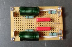
It doesn't have a Thiel or zobel so I made one on a perfboard. A couple of coils. 4 10R resistors and a couple 100n caps. Simple but it works.
It have Speaker Terminal with Zobel Network and triac DC protect in this thread post #43 and #55.
Last edited:
The amplifier output Zobel is ONLY a VHF load, to help with stability, so that the amplifier does not see a very high impedance at VHF.
To achieve an effective VHF load the Zobel MUST be located in the amplifier such that the trace route from output devices through the Zobel and back to the Decoupling ground is VERY SHORT.
The Zobel part of the Thiele Network does not get located off PCB.
The Inductor part of the Thiele Network can be located off PCB.
If you adopt the Pi version with 2 Zobels, then the first Zobel is on PCB (it is the VHF load), the second Zobel is at the Chassis mounted speaker terminals. This is the best place to attenuate RF interference coming in via the output cables.
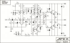
Apex SR100F...not tested.
Nice schematic, thanks.
Apex SR100F...not tested.
Use 100R pot instead R9, R10 (47R) to set dc offset.
Attachments

- Home
- Amplifiers
- Solid State
- Studio Reference Amplifier