Hi desertstorm.
Remove fuses.Replace them with 2 resistors. 10-22R.
Power PRIMARY side of transformer via 220v lamp.in series.
If the lamp glow remove the power cord and examine all the circuit for wrong placed parts or short circuits .
If lamp is dark you are on the right way.
Measure voltages on test resistors(these in place of fuses)you must see low voltages about 2v or something about it.
If you see high voltages ,something like 5v there is a problem.You must examine for faults again.
Suppoce you measure 1-2v.Measure amplifier out ,you must see 0v d.c or something as 20-100mv d.c.
If you measure 42v you have a problem.
If you measure 0v or 20-100mv d.c measure again but for a.c volt .
If you measure any A.C volt here(without any inp.signal)your amplifier oscillate
Hope these are usefull.
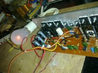
sir here is the pic. of my ongoing project...
Attachments
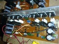
sir here is the pic. of my ongoing project...
SIR, offset out 0.0 i try also valve light, the light is dim sir..but 10r/2w resistor next to coil is hot very hot..sir..


MEASURE THESE VOLTAGES.
Change fuses with resistors.
Measure resistors voltage ,without any input signal not speaker on output.
It seems like oscillations.
Did you have an oscilloscope?
Offset is d.c voltage
Oscillation is a.c voltage
Measure on a.c range.
Change fuses with resistors.
Measure resistors voltage ,without any input signal not speaker on output.
It seems like oscillations.
Did you have an oscilloscope?
Offset is d.c voltage
Oscillation is a.c voltage
Measure on a.c range.
Attachments
Last edited:
Change fuses with resistors.
Measure resistors voltage ,without any input signal not speaker on output.
It seems like oscillations.
Did you have an oscilloscope?
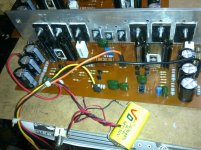
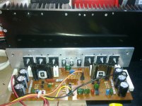
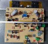
sir, here some pic of my project...thank you so much for your help sir, i give you an update thank sir and more power...
Attachments
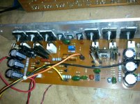
SIR, offset out 0.0 i try also valve light, the light is dim sir..but 10r/2w resistor next to coil is hot very hot..sir..
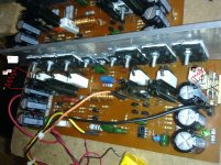
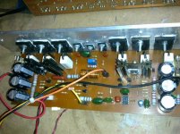
On this pcb C2 100pF missing
thanks Apex.
Amplifier oscilate in h.f because no input filter present.
Look at this photo,c2=100pf(inp.filter missing).
thank you so much sir apex and sir thimios for your help...i find out the missing cap. 100pf in the diagram...thanks so much ...i try to fix it...god bless and more power....
thank you so much sir apex and sir thimios for your help...i find out the missing cap. 100pf in the diagram...thanks so much ...i try to fix it...god bless and more power....
Sir Miles, sir Alex and sir Thimios thanks you so much you all ..now my amp.start shaking ng room thank you so from the bottom of my heart....
Attachments
Sir Miles, sir Alex and sir Thimios thanks you so much you all ..now my amp.start shaking ng room thank you so from the bottom of my heart....
You must say thanks to Mr. Mile.
He has seen the 100pf missing capacitor.
Sir mile thank you so much sir, Sir thimios and sir alex thank you so much...god bless you all....You must say thanks to Mr. Mile.
He has seen the 100pf missing capacitor.
Sir mile thank you so much sir, Sir thimios and sir alex thank you so much...god bless you all....
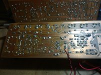
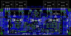
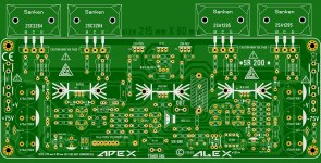
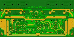
New PCB for Sanken's transistors V3.3
.....another PCB for Sankens , have split Q7 from Q8 ....
and I need to check somebody if it's OK , and then I will post layout in black and white and the rest of files .
Regards ,Alex
.....another PCB for Sankens , have split Q7 from Q8 ....
and I need to check somebody if it's OK , and then I will post layout in black and white and the rest of files .
Regards ,Alex
Attachments
Thats good news!.....another PCB for Sankens , have split Q7 from Q8 ....
and I need to check somebody if it's OK , and then I will post layout in black and white and the rest of files .
Regards ,Alex
Hi Guys,
I see some of you have working models so this amp must work but I am struggling to get mine going. I'm not getting any signal through to the output. As a matter of fact I have too much interference on the input to even get a clean reading on the scope there. I'm using an NTE 941M for the servo and that may be part of the problem I'm not sure. I tried building a spice model but it is showing as bad of results as I am getting from my amp. I am attaching the spice model and Cordell models. If one of you who knows ltspice could take a look, maybe you can find the issue. I would like to get it working so I can use it to trouble shoot my boards.
I built the amp from the foil pattern in post 1625. There are two 100n caps on the board that are not in the schematic. I added those to the spice model. Any help appreciated.
Blessings, Terry
Attachments
Hi Guys,
I see some of you have working models so this amp must work but I am struggling to get mine going. I'm not getting any signal through to the output. As a matter of fact I have too much interference on the input to even get a clean reading on the scope there. I'm using an NTE 941M for the servo and that may be part of the problem I'm not sure. I tried building a spice model but it is showing as bad of results as I am getting from my amp. I am attaching the spice model and Cordell models. If one of you who knows ltspice could take a look, maybe you can find the issue. I would like to get it working so I can use it to trouble shoot my boards.
I built the amp from the foil pattern in post 1625. There are two 100n caps on the board that are not in the schematic. I added those to the spice model. Any help appreciated.
Blessings, Terry
Hi Terry,
There are two mistakes in your model:
- R19 must be 1meg (not 1m);
- Q10 must be BC560C (not bc550C).
After corrections it runs fine
Cheers,
Valery
Hi Valery,
Thanks, that fixed it.
Hey Maxwell,
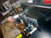
I much prefer board house boards but I'm getting a stack of extra boards so I have resolved to etching lately. I etched and filled a pair for this amp and neither are working. Hopefully having a working spice model will elp me get to the bottom of it.
Blessings, Terry
Thanks, that fixed it.
Hey Maxwell,
I much prefer board house boards but I'm getting a stack of extra boards so I have resolved to etching lately. I etched and filled a pair for this amp and neither are working. Hopefully having a working spice model will elp me get to the bottom of it.
Blessings, Terry
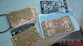
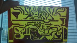
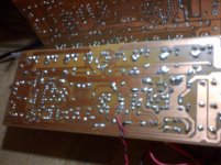
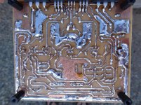
These were very poor boards. Radio Shack double sided. The substrate is very brittle and blows out easily. The pitting in the copper is due to poor iron transfer and long etching time to remove the second side. I won't use these again. It's unlikely any of my home etched boards will ever find their way into an amp case. They are strictly for learning.
Blessings, Terry
Blessings, Terry
- Home
- Amplifiers
- Solid State
- Studio Reference Amplifier