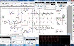
Nice work done Aniket,
Can you please post multisim file and sprint file of your this final modified version, one more question, how did you get 2sc5200 and 2sa 1943 model files , and njw also.
Thanks Sir,
I am using Multisim 13, it has models for almost all Onsemi audio BJT's.
Models for 2SC5200/A1943:
Toshiba:
.MODEL 2SC5200 NPN (
+ IS=3.0463E-11 BF=96.20 VAF=100 IKF=15.04256 ISE=5.6190E-11 NE=2.0 BR=4.849 IKR=1.05012 VAR=100 ISC=7.18E-8 NC=1.5 RE=0.0025
+ RB=20.18 RBM=0.0014 IRB=1.0E-7 RC=0.01137 CJE=4.5000E-10 CJC=8.4915E-10 VJC=0.68977 MJC=0.54081 TF=6.8583E-10
+ XTF=9.5721 VTF=10.425 ITF=6.8697E-2 TR=1.000E-8 XTB=1.45 EG=0.82 FC=0.5 mfg=Toshiba)
.MODEL 2SA1943 PNP (
+ IS=1.30E-10 BF=91.42 VAF=100 IKF=4.480 ISE=1.02E-10 NE=2.0 VAR=100 ISC=5.0900E-9 NC=1.5 BR=0.882 IKR=2.9015 RE=0.0011
+ RC=0.0553 RB=140.05 RBM=0.0041 IRB=8.5e-9 CJE=2.00E-10 FC=0.5 CJC=9.45E-10 VJC=0.48 MJC=0.28 TF=9.250E-10 XTF=10 VTF=10
+ ITF=1 TR=1.00E-8 EG=0.76 XTB=2.68 mfg=Toshiba)
Fairchild:
.MODEL 2sc5200fc NPN (
+ IS =4.3031E-12
+ BF =152.1
+ NF =1.0
+ BR =6.155
+ NR =1.028
+ ISE =1.3924E-11
+ NE =1.5
+ ISC =2.7542E-11
+ NC =1.95
+ VAF =60.0
+ VAR =6.51
+ IKF =10.8637
+ IKR =0.1585
+ RB =2.47
+ RBM =0.02
+ IRB =0.08
+ RE =0.04
+ RC =0.015
+ CJE =5.8111E-9
+ VJE =0.6506
+ MJE =0.3357
+ FC =0.5
+ CJC =6.4394E-10
+ VJC =0.5
+ MJC =0.3966
+ XCJC =0.7624
+ XTB =1.0445
+ EG =1.1663
+ XTI =3.0 )
.MODEL 2sa1943fc PNP (
+ IS =3.5476E-11
+ BF =159.9
+ NF =1.0
+ BR =25.75
+ NR =1.011
+ ISE =2.5119E-10
+ NE =2
+ ISC =7.9433E-11
+ NC =1.37
+ VAF =60.0
+ VAR =11.07
+ IKF =2.8370
+ IKR =0.3548
+ RB =2.74
+ RBM =0.0381
+ IRB =3.6308E-3
+ RE =0.06
+ RC =0.01
+ CJE =4.1783E-9
+ VJE =0.6354
+ MJE =0.3374
+ FC =0.5
+ CJC =1.1383E-9
+ VJC =0.5
+ MJC =0.3699
+ XCJC =0.7624
+ XTB =1.5306
+ EG =1.1751
+ XTI =3.0 )
Simulation and sprint files are attached.
Regards,
Aniket
Attachments
check it
Thanks Aniket,
for multisim 13 files and models of 5200 and 1943, I have tried to modify your circuit, Now with lowest distortion from 20 hz to 20 khz and more output voltage wattage, i will be thankfull if you can post 4793 and 1837 models and include them in a multisim file so can be easily saved. attached is modified.
Attachments
here pdf alslo
Hi Aniket,
Here is pdf also of your circuit now modified, I am on facebook https://www.facebook.com/vedmitraa
Hi Aniket,
Here is pdf also of your circuit now modified, I am on facebook https://www.facebook.com/vedmitraa
Attachments
Thanks Aniket,
for multisim 13 files and models of 5200 and 1943, I have tried to modify your circuit, Now with lowest distortion from 20 hz to 20 khz and more output voltage wattage, i will be thankfull if you can post 4793 and 1837 models and include them in a multisim file so can be easily saved. attached is modified.
Hello Sir,
It could be improved a lot more. simulation models for 2SC4793/A1837 could be saved from the attached simulation file.
Hi Aniket,
Here is pdf also of your circuit now modified, I am on facebook https://www.facebook.com/vedmitraa
We are already friends there
")
Thanks,
Aniket
Attachments
Hi Aniket . Diodes D3 and D4 . I wonder how they came to be there ? Might a 2200 uF 100 V serve well the other side of D3 D 4 to the power devices . You might even replace the diodes by resistors loosing 1 V if so . This would make the VAS supply slightly smoother . In truth even 5 V lost would be OK . A switch to choose perhaps ? You should find clipping is slightly nicer if the driver clips first . Just a thought as it would cost almost nothing to try .

The 741 could be upgraded a bit. I think TL071 is a place to start. If NE 5534 I would expect it to need compensation as in the application notes. OP604 perhaps? The design can be improved with a Baxendale diode. The red circle is one. The text below shows the improvement.
Improving the Sansui 2000x Receiver Power Amp Section

Improving the Sansui 2000x Receiver Power Amp Section
If you look at the example amplifier I give it is an all NPN output. The other an all PNP. 30 years ago such and idea would have been rejected as NPN would be faster and more rugged.
In the early 1960's all PNP germanium designs were common, the PNP being the better device when germanium.
The only commercial PNP silicon design I ever saw was Goodman's Module 80. Rumour has it a modified germanium circuit to use silicon 2N2955.
My only guess is the designer of this new amp could buy the 2SA1494 at a good price so deliberately set out to build something very slightly wrong. The desire to be different ? As the modern all PNP output stage will function to a good standard it is not so bad to do it. The very weird thing is a PNP+ NPN output stage would have been easier to design and cost less usually.
If a Baxendale diode is fitted the output stage will need reinterpreting as PNP. In view of that I wouldn't bother. Also the amplifier seems to have no way of accurately setting bias / standing current.
This design looks good. Remember the amplifier cost is often 80 % power supply and casework plus heat-sinks. Buying the very best electronics is going to change price by 10% at a good guess? The nice thing about Rod Elliot's amp is it is so easy to understand. The distortion is virtually zero. Bias can be set by ears! Even at zero bias it works well up to 10 kHz. I suspect better than the all PNP amp when that. Reset to 100 mA standing current should be perfect ( 20 to 100 mA will work ).
Project 101 - High Power, High Fidelity Lateral MOSFET power amplifier
hi,guys...I have built it ..its clean nd power full sound...if someone interested to built 100w amps..then I suggest him please built this ..nd trust me..
Hi, pallab!
PCB for circuit are there?
hey,mikrocxema.i am not a pcb expart..but i draw a pcb useing eagle softwire..
https://www.facebook.com/photo.php?...129.1073741838.100001260869231&type=1&theater
https://www.facebook.com/photo.php?...129.1073741838.100001260869231&type=1&theater
Easy 100 Watt Power Amplifier | Amplifier Circuit
Here is another example. Not unlike early B&O amplifiers. What looks old fashioned works very well. In the old days a small resistance might have been added between D1 D2 to adjust standing current ( 7 mV across R 9 or R10 would be about right, if too high try different diodes) . Worth a thought.
Velleman sell a kit much like this.
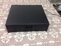
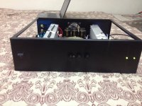
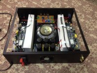
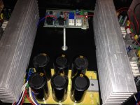
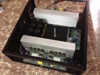
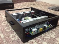
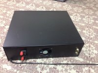
My new build, used a 45-0-45, 750VA toroid and 3x15000uF caps per rail. output devices are njw3281/1302 in place of 2SC5200/A1943, replaced MJE340/350 with KSC3503E/1381E in VAS duty. with these mods amp puts out 300W+ per channel into 4 ohms.
Attachments
-
 IMG_0989.JPG295.4 KB · Views: 96
 -
 IMG_0987.JPG230.8 KB · Views: 166
 -
 IMG_0986.JPG436.7 KB · Views: 232
 -
 IMG_0985.JPG361.4 KB · Views: 553
 -
 IMG_0984.JPG238.4 KB · Views: 577
 -
 IMG_0979.JPG295.6 KB · Views: 584
 -
 IMG_0977.JPG266.7 KB · Views: 596
 -
 IMG_0983.JPG384.1 KB · Views: 639
 -
 IMG_0990.JPG256.9 KB · Views: 98
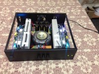
Nice work Aniket, pity the heatsink fins run parallel and not vertical.
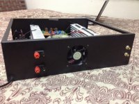
Are there air vents on the sides of the enclosure, I see a fan pushing air into the enclosure, (btw I believe the primary fan should blow onto the circuit and not pull air away from the circuit.) But there are no entry points for air visible.
Would be great if you had two fans blowing into each heatsink
But you can judge by how hot the heatsinks get when playing music for a hour or two with the enclosure closed.
lol, I hate it when other people criticize another man's hark work, this is not my attention.
What preamp circuit did you use?, I'm still looking out for a diy one that suits my needs
regards
Hi Aniket. I am building a similar monster amp closer to the Quad 303 ( MJ15015 ). I too must run the heat sinks this way. If you spray paint them black except the transitor area you might loose 10 % more heat. Some paints are designed to etch and cover. Even grey works! My one 90 watts for now.
Very nice work.
Very nice work.
Thanks All,
Air vents are on the sides of the enclosure, I placed the heatsinks in a way that they form a tunnel for the the air to flow between them, thereby cooling them. fan is to exhaust hot air outside. i could feel air sucking in through vents.
I had ran the amp at high power continuously for 2-3 hrs several times, never got the heatsinks more than just warm, never felt hot air from the exhaust fan. bias is 50mA per transistor.
Preamp i used is Rod Elliott's P97, made it on a veroboard, it's a very good sounding preamp, credits to Rod for the excellent but simple design.
Regards,
Aniket
- Status
- This old topic is closed. If you want to reopen this topic, contact a moderator using the "Report Post" button.
- Home
- Amplifiers
- Solid State
- Simple 100W power amp