HI Andrew T
I use typically 250mV as well, but some of my other designs have also worked well with just 100mV. Keantoken's point about matching resistors is a good one, but with 1% MO resistors these should be stable enough. Carbon film though cheap generally have a higher TCR which again should not really matter much when the voltages across them are the same.
In good balanced design matching is all about keeping power dissipation levels the same- as Keantoken also mentioned, but my concern about the single ended VAS is that even with a Darlington transistor the currents in the CM are not balanced. Using differential VAS stages has an advantage in not only can currents be balanced more accurately but also the current in overload conditions can be controlled.
John
It is easy to load the secondary permanently with a capacitor to prevent saturation while not consuming any actual power. My question is, how large a capacitor is necessary, and how much VA of the transformer does it waste?
I think you would have to measure trafo temperature or probe the magnetic field to find out unless you had a sophisticated power draw measurement.
I think you would have to measure trafo temperature or probe the magnetic field to find out unless you had a sophisticated power draw measurement.
Gone back through to post901 and can't find any post that I sent, that matches with this comment.I use typically 250mV as well, but some of my other designs have also worked well with just 100mV.
Are we talking about voltage drop across degeneration resistors?
When was that?
How does a capacitor across the secondary of a main transformer prevent saturation?It is easy to load the secondary permanently with a capacitor to prevent saturation while not consuming any actual power. My question is, how large a capacitor is necessary, and how much VA of the transformer does it waste?
I think you would have to measure trafo temperature or probe the magnetic field to find out unless you had a sophisticated power draw measurement.
Magnetic Saturation is a voltage thing.
What are you trying to find out?
Dear John Ellis,
to which post...
... can't find any post that I sent, that matches with this comment.
Seems to be post #10 - about 14 months back!
It was about values for current mirror resistors.
I remember this discussion because I recommended increased potential drop across the current mirror resistors, contrary to Slone and Self.
Toni tested and found that the increased value worked better.
Best wishes
David
What I read was that saturation happens without a load, and that when you load the secondary the saturation stops. During most of the sine when the rectifiers aren't conducting, there is no load on the transformer. Putting a cap across the secondary provides a minimum load.
I am glad I stopped at post901 !
Groner has also looked in detail and confirmed that very high Vdrop on the mirror resistors is useful and NOT noisy.
So we have Toni and Groner and Zan and Ellis all agreeing that higher Vdrop is an advantage.
Can't recall what Cordell has to say on the degen resistance?
Groner has also looked in detail and confirmed that very high Vdrop on the mirror resistors is useful and NOT noisy.
So we have Toni and Groner and Zan and Ellis all agreeing that higher Vdrop is an advantage.
Can't recall what Cordell has to say on the degen resistance?
Can't recall what Cordell has to say...
Bob does not actually say much at all, but seems to know about it, because the values he shows in his examples are reasonable, much better than Self.
I noticed this effect in simulation myself and then had Samuel's work pointed out to me. So he's the one to credit, he in turn, has references to the primary work by Bilotti. I just pointed it out to Toni.
Also Samuel has a helpful analysis that mostly dismisses John Ellis's concern about balance. I expanded on that work a little in Richard Lee's thread about Cherry amplifiers.
Best wishes
David
I like the idea of large resistors here, but AFAIK the LTP BJTs contribute an equal amount of noise and degeneration doesn't improve that, so there's not a lot to gain. Performance improvements of less then 6db are readily swamped by manufacturing variations.
Also, very large degeneration limits the transistor speed. I guess that's not an issue with most amps though. With RFI 300MHz and up it may improve EMC.
Also, very large degeneration limits the transistor speed. I guess that's not an issue with most amps though. With RFI 300MHz and up it may improve EMC.
Leach used 300r as degeneration for his LTP.
Went into a lot of detail of why that much degen was needed.
Yes, LTP degen increases noise. Some extra noise is swapped for better performance in other areas. Compromise as usual.
But in the mirror load for the LTP, extra degen does not increase the noise. It actually reduces the noise and improves the performance in some other areas.
If the noise (before the added degen) is 20dB below the audible noise floor and we increase that noise to equal the audible noise floor, does that make a big, or little, difference to the sound quality we hear?
If the noise increase is to 10 dB below the audible noise floor, does that reduce the sound quality we hear a little bit, or not at all?
Last edited:
...AFAIK the LTP BJTs contribute an equal amount of noise...
The LTP noise is not necessarily equal, one needs to do a careful noise analysis.
Of course the LTP will still contribute some noise but the decrease in the noise from the current mirror is essentially "free" - Lower noise from a smarter choice of values.
...limits the transistor speed. I guess that's not an issue with most amps...
It is possible to add capacitor bypass of the CM emitter resistors to cancel this.
It looks potentially beneficial for a fast amplifier but I have done simulations and the results are not entirely obvious.
Any ideas welcomed.
Best wishes
David
Last edited:
What I meant was that with half of the noise coming from the LTP and half from the CM, reducing most of the CM noise is not going to improve noise more than half.
If you have large LTP degeneration, the mirror noise will matter much much more. I didn't think of this at first because I rarely use much LTP degeneration.
Large CM degeneration is usually a good idea, maybe even mandatory if your LTP is degenerated. But if your LTP isn't degenerated it won't be much of an improvement, so I focus on other parts of the design.
EDIT: You've studied this much better than I have Dave. The designs I've been working with haven't liked degeneration much, but for a lot of circuits, it's like you say - free improvement.
Last edited:
I am glad I stopped at post901 !
Groner has also looked in detail and confirmed that very high Vdrop on the mirror resistors is useful and NOT noisy.
So we have Toni and Groner and Zan and Ellis all agreeing that higher Vdrop is an advantage.
Can't recall what Cordell has to say on the degen resistance?
 .
.Current mirror Vdrop in latest input stage version is about 500mV which results in lower noise. Real life tests also showed: going higher with Vdrop and slew rate begins to become asymmetrical.
It's actually the other way round.If you have large LTP degeneration, the mirror noise will matter much much more. I didn't think of this at first because I rarely use much LTP degeneration.
Loadsa LTP degeneration means the input LTP contributes loadsa noise so the mirror noise is less important.
The definitive treatment is in Groner's critique of Self's book .. essential reading for all PA gurus and wannabe gurus.
Bigger mirror degeneration resistors give less noise but too big and the mirror has problems doing its job ... introducing reduced & assymetrical slew.
Kean's recommended BJTs which perform well at low Vce help a lot here.
I like to keep Vce in the mirror transistors about the same for no signal but it really only makes a difference when you get to single figure ppm THD
What I read was that saturation happens without a load, and that when you load the secondary the saturation stops. During most of the sine when the rectifiers aren't conducting, there is no load on the transformer. Putting a cap across the secondary provides a minimum load./QUOTE]I say in #1060, as the core approaches saturation (as input voltage increases), the Magnetisation (no load) current starts increasing rapidly and becomes very contaminated with odd order harmonics.
Putting a load on the secondary simply hides this distorted increased Magnetisation current under the load current. It doesn't reduce it.
You can easily check this if you have a Variac. NOTE DAVE ZAN'S CAVEATS ABOUT PLAYING WITH MAINS!
This happens with ALL 'iron' (including mumetal bla bla) core transformers without air gaps.
You can simulate this safely with a line level iron core transformer by simply feeding it 50Hz and increasing the input voltage with no load. Or even by driving the secondary of a 12V:240V or 12V:110V mains transformer leaving the primary open circuit.
Use a power amp. Source resistance will complicate matters.
Oops I must stop using the Tardis.
Regarding mag saturation - the transformer coil should have enough turns that the core does not saturate. With a load the secondary current is balanced by an increase in primary current and to a first order the magnetic fields should remain constant.
And whenever I build my own transformers I usually keep the magnetising current low so that even at highest mains voltage the core will not saturate. Some companies offer a "low mag" option too for cool running/higher reliability.
John
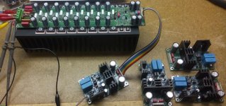
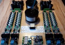
... just finished 4 pieces of input vas modules v3.4
All 4 modules are working out of the box without any problems.")
All 4 modules have nearly identical distortion figures.
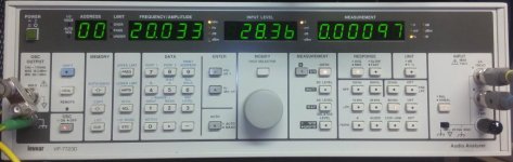
Attached a distortion quick check:
0.00097% THD+N 20kHz @ 100W @ 8R
BR, Toni
All 4 modules are working out of the box without any problems.
All 4 modules have nearly identical distortion figures.
Attached a distortion quick check:
0.00097% THD+N 20kHz @ 100W @ 8R
BR, Toni
Attachments
- Home
- Amplifiers
- Solid State
- 2stageEF high performance class AB power amp / 200W8R / 400W4R