Still in the process to build low power version, decided to improve the clipping behavior.
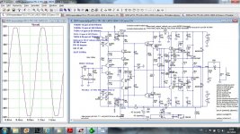
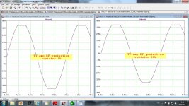
I simulated two VAS types, EF enhanced, and Baxandall supper pair. Baxandall super pair produced a bit higher THD20k, but clipped very gracefully. To improve clipping of the EF enhaced VAS I increased EF transistor protecting resistors from 1k to 5k6 (R24, R29) and here is result. It shows that to get better clipping behavior that protection resistor should be of quite high value. This is valid for a single VAS in VFA amps, specially with TMC, or TPC.
Damir
Attachments
I simulated two VAS types, EF enhanced, and Baxandall super pair...
Hi Damir
I have just looked at this issue because of another thread.
The actual amp in that thread was very bad, but it made me wonder why Baxandalls don't perform as well as one hopes.
Perhaps they could be improved with a diode or two to increase the Vce of the input transistor.
I plan to test this later, have you tried this?
Reason I asked is because I also experimented with the value of the resistor in the EF version, as you have done.
My reason was mainly to reduce power dissipation for better thermal balance.
I found the resultant variation in Vce here had a side effect on distortion, it made more difference than I initially expected.
And what models do you use for your output FETs?
Distortion simulation is very sensitive to this, of course.
Found another thread where they simulated absurdly low distortion, all because of useless FET models. I hesitate to spoil their illusions
")
Best wishes
David
Hi Damir
I have just looked at this issue because of another thread.
The actual amp in that thread was very bad, but it made me wonder why Baxandalls don't perform as well as one hopes.
Perhaps they could be improved with a diode or two to increase the Vce of the input transistor.
I plan to test this later, have you tried this?
Reason I asked is because I also experimented with the value of the resistor in the EF version, as you have done.
My reason was mainly to reduce power dissipation for better thermal balance.
I found the resultant variation in Vce here had a side effect on distortion, it made more difference than I initially expected.
And what models do you use for your output FETs?
Distortion simulation is very sensitive to this, of course.
Found another thread where they simulated absurdly low distortion, all because of useless FET models. I hesitate to spoil their illusions
Best wishes
David
Hi David,
I manipulated the EF protection resistor for the same reason as you did, to reduce power dissipation for better thermal balance, but then it came to my mind that it could be used to better clipping behavior too. By the way in my opinion the way D. Self is using overcurrent protection transistor is not good enough without that EF protection resistor.
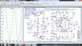
I simulated Baxandalls as you suggested and I've got lower distortion (needed to change some resistors value to keep the same bias), and a bit worsen clipping.
I use Cordell's output MOSFET models. I know they are not good enough but I don't have better ones.
best regards
Damir
Attachments
It also needs to be high to stop it dying & killing the VAS, driver, OPS ...To improve clipping of the EF enhaced VAS I increased EF transistor protecting resistors from 1k to 5k6 (R24, R29) and here is result. It shows that to get better clipping behavior that protection resistor should be of quite high value.
on overload. Don't ask me how I know It also needs to be high to stop it dying & killing the VAS, driver, OPS ...
I was following D. Self power amp distortion articles in WW long time ago. That was all very well explained, never surpassed by anyone even now. I've learned a loot from that and have built my first blameless then. During some transient overload VAS transistor was burned. It was EF enhanced VAS. I added a resistor between the collector of the EF transistor and the ground, if I remember correctly it was 220 R, and after that VAS never failed. That was 30 years ago, I think, and still I have all WW numbers from that time.
I am a bit perplexed that D. Self still does not use that resistor!!
Later on I learned that this resistor has to have even higher value.
Damir
... I simulated Baxandalls...lower distortion... and a bit worsen clip...
Yes, it does seem that the increased drop across the transistor improves the distortion and worsens the clip, both for Baxandall and EF enhanced.
Presumably the transistor can be pushed further into saturation, probably that is obvious once you think it out.
I will have a think.
I use Cordell's output MOSFET models...I don't have better ones.
I recommended Toni replace some of his PMOS/NMOS models with VDMOS (like Bob 's) and they made a pretty accurate prediction of distortion, even if theoretically not as accurate as a combined VDMOS plus EKV model. So you are most of the way there.
... the VAS, driver, OPS ...
Yes, haven't done this but know it happens. The value I use for thermal reasons also fixes this.
..I am a bit perplexed that D. Self still does not use that resistor!!
Me too. It is already in the draft for my book
Best wishes
David
Last edited:
I pointed out to Self that some of the designs in the 4th edition of the book would self destruct. He acknowledged that was the case.I am a bit perplexed that D. Self still does not use that resistor!!
Later on I learned that this resistor has to have even higher value.
This was in the thread where he asked for suggestion for his latest edition.
Dunno if the latest 6th ed makes these corrections. Anyone here have this latest edition?
Last edited:
6th edition still shows the collector resistor as "does not exist".I pointed out to Self that some of the designs in the 4th edition of the book would self destruct. He acknowledged that was the case.
This was in the thread where he asked for suggestion for his latest edition.
Dunno if the latest 6th ed makes these corrections. Anyone here have this latest edition?
Some Members have reported increased distortion as the collector resistor value is increased from 0r0.Yes, it does seem that the increased drop across the transistor improves the distortion and worsens the clip, both for Baxandall and EF enhanced..................
Another Member recently suggested bypassing the Collector resistor with a largish Capacitor.
Some Members have reported increased distortion as the collector resistor value is increased from 0r0.
Another Member recently suggested bypassing the Collector resistor with a largish Capacitor.
A zener across the C-E of the EF can shunt the Cob and control the power dissipation of the EF at the same time. I saw the use in probably Toni's 2EF amp thread.
A zener across the C-E of the EF can shunt the Cob and control the power dissipation of the EF at the same time. I saw the use in probably Toni's 2EF amp thread.
That was a very good tip from wojtek5001. This replaced the VAS protection resistor starting with post #801. For the latest refinement see post #979
The VAS power transistor has been doubled to fulfill SOA requirements due to high VAS current. This variant performs very well and extrem overload simulations showed no SOA violations at all.
Using a bypass diode D4 (schematic from 2stageef post #979) also fixes a blameless VAS typical bad clipping behaviour.
BR, Toni
Last edited:
Using a bypass diode D4 (schematic from 2stageef post #979) also fixes a blameless VAS typical bad clipping behaviour.
BR, Toni
A diode in that place increases distortion with its nonlinear capacitance.
Damir
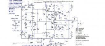
I don't think it's necessary to complicate to much, here is my VFA TT amp where EF protection resistor was increased from 1k to 10k with no increase in distortion and much better clipping behavior, 1k was enough to protect EF and VAS from overload.
Damir
Damir
Attachments
A diode in that place increases distortion with its nonlinear capacitance.
Damir
Of course it does - one must decide what is more important.
OTOH my real life measurements THD+N 20k@200W@8R (bw 80k) - 0.0016% are made including this diode - so what are we talking about...
I don't think it's necessary to complicate to much, here is my VFA TT amp where EF protection resistor was increased from 1k to 10k with no increase in distortion and much better clipping behavior, 1k was enough to protect EF and VAS from overload.
Damir
AFAIK: simulation has problems to show a correct clipping behaviour as the sim models don't take bjt saturation into account. Testing my amplifier without diode in real life also showed a good clipping behaviour a 1k but not running 20kHz ...
Some Members have reported increased distortion as the collector resistor value is increased from 0r0.
Yes, this is what I found, I just wrote it the other way round.
{reduced resistor} leads to "increased drop across the transistor improves the distortion".
bypass... the Collector resistor...
I have tried this and found it can be helpful
... as the sim models don't take bjt saturation into account.
There are saturation parameters, usually not used.
This is Keantoken's pet subject, a search will find useful information.
But didn't we practically solve this with correct values of junction capacitance? I remember I made a recommendation of the parameter and value and then you and Richard tuned the value to match your measured results. Richard was not entirely happy but didn't it match pretty well for you?
Best wishes
David
...tip from wojtek5001. This replaced the VAS protection resistor...i
Hi Toni
I did not pay sufficient attention to this at the time so thanks to Nattawa and you for the reminder and wojtek5001 for the idea.
The reason I skipped over it is because I have efficient speakers so clip and overload behaviour are not a major issue.
But it is very educational because it separates the effect of the altered Vce from the effect of the lower (dynamic) resistance shunt of the transistor capacitance.
I now realize my reply to Andrew focussed on only one aspect.
The zener allows optimization of both variables, seems an excellent solution.
Many issues and some subtleties in just one connection, it's definitely in my book notes.
Best wishes
David
Last edited:
...
But didn't we practically solve this with correct values of junction capacitance? I remember I made a recommendation of the parameter and value and then you and Richard tuned the value to match your measured results. Richard was not entirely happy but didn't it match pretty well for you?
...
It bettered significantly but not cured the problem.
Back to the initial version of 2stageef: 1kHz clipping was nearly invisible on osci screen and IMHO the very very short clipping artefacts wouldn't kill a tweeter. Of course 20kHz clipping was viewable.
20kHz @ half power would have killed the tweeters long before the clipping problem...
A simple diode solves this luxury problem at the cost of a few ppm added distortion. So one can decide himself what is more important.
I would like to see real live pictures of 20kHz clipping behavior of other amplifiers but haven't found anything so far...
BR, Toni
Last edited:
...
Many issues and some subtleties in just one connection, it's definitely in my book notes.
...
... and this solution also allows to use transistors which have better saturation behavior but unfortunately low Vce.
BR, Toni
Last edited:
... but not cured the problem...
Hi Toni
Just to clarify, I meant that it mostly solved the problem to make the simulation match the reality.
Not that it cured the problems when the amplifier actually clipped.
I like Damir's work on this, I know in the Ovidiu/Stuart amplifier that one of the major difficulties was to ensure clean clip behaviour without adverse effect on the ultra-low distortion under normal conditions.
So it is not a simple problem
Best wishes
David
- Home
- Amplifiers
- Solid State
- 200W MOSFET CFA amp