Well, today I tried to test an amp that uses switching power supplies. It overloaded my HP39 analyzer. That is too much.
Figures noise spectrum etc, sounds like a badly designed piece of gear, SMPSs are used on some very sensitive analogue stuff with no problems when done properly, generalisation is not a good thing....
I stumbled across this, while exploring references to micro-cracks: Untitled. Many would suggest this belongs in the Funniest snake oil theories thread - but, is there something in it?
You are correct the wrong thread......
How does a signal propagate down a cable? electrons travel very slowly when this is happening 0.1mm/s or so, bumping in to everything in their way, would a few micro cracks affect them, nope, would the micro cracks affect the TEM wave, nope.
Good to see they mention space for the wire, goto be good if its used for aerospace.
Looked at the EMC results, those are well dodgy.....
Last edited:
From your post, your capacitance readings were the very low end of the resolution of the specific scale your meter was running. Saying something is .0015 nF instead of 1.5 pF tells me you're using the last few digits of the range. So a better meter, capable of sub pF measurements, is the way to go. If you do not get readings in the 5 to 30 pF per foot, you are most likely being lied to by the machine.Yeah I'll rerun it Thursday with a different bridge. But if the capacitance reading is staying the same so should the inductance.
As to low frequency inductance, it is not possible to have a twisted pair of wires exceeding 200 nH per foot. And that is with very thick insulation. You need to realize that if you're three orders of magnitude away from 150 to 200 nH per foot, that you're measurement apparatus is lying to you. Stop the test, and figure out why it's lying to you. Do NOT continue with the data, as the data is absolutely WRONG. BAD data leads to bad conclusions.
These are very simple two terminal measurements. You must learn when to consider very bad data as suspect, I should not have to be the one to explain it to you.
Still no response on my thought about two ways of twisting? Imagine the insulation having an identifying stripe running along it, which always has the same orientation along its length, ie., doesn't spiral around the conductor: in twist 1 the stripe always stays, say, on the outside of the twisted pair, is always visible - this is what will nominally happen using a drill; in twist 2 the stripe spirals to the inside and outside of centre of the twisted pair, but from a distance the stripe constantly faces a certain direction.
The 'stress' on the cable is different in the two cases - does this make a difference, in any audible area?
As I earlier stated, by twisting with the far end locked, the conductors will be twisted as well as the bundle. By allowing the ends to be loose, the conductors will not internally twist. The distinction becomes apparent when tension is released, as the bound end pair will loosen up, allowing the conductor spacing to increase whereas the free end one will remain tighter.
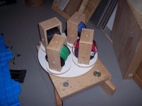
About ten years ago, I made a twist fixture for 4 #12 awg wires, it had 4 independently rotatable spool holders on a larger diameter platform. I had the option of locking the spools to the platform, rotating them at the opposite rate as the platform to eliminate conductor twist, and rotating them faster in the opposite direction, which forced the conductors to be twisted but in a way that the conductor trying to untwist forced the bundle tighter..
Here's a picture of it early into the build. Don't know where the final pics are..

jn
ps..Ed, why can you not measure resistance at that level? 24 gauge is 27.7 milliohms per foot, or 55 milliohms per foot for a pair. Any 4 wire meter should be capable of measuring this value to an accuracy of a milliohm or two.
Attachments
Last edited:
Ed has been maintaining that the lower current density operation is responsible, and it lowers as current density goes up. Smaller wires therefore go in the wrong direction.I think the thinner the wire, the greater the affect.
THc-RNMarsh
jn
I didn't check but am pretty sure his SR1 has an internal measurement filter for things like this (even an AES17 would work) but you also need an external one to avoid overloading the analyzer input circuits.
John why are you using an HP39 (339?) instead of your new toy?
Jan
Yes I have one, a seperate box wide and thin to sit under the AP.
Ed has been maintaining that the lower current density operation is responsible, and it lowers as current density goes up. Smaller wires therefore go in the wrong direction.
jn
The elephant in the room is still that the distortion expressed as a voltage in the loop should appear across the wire alone. So measure there and eliminate the dynamic range and analyser residual issue.
The elephant in the room is still that the distortion expressed as a voltage in the loop should appear across the wire alone. So measure there and eliminate the dynamic range and analyser residual issue.
Perhaps the worst case distortion will occur when only one single electron is moving..
jn
Yes I have one, a seperate box wide and thin to sit under the AP.
Scott do you have the original AP box?
The elephant in the room is still that the distortion expressed as a voltage in the loop should appear across the wire alone. So measure there and eliminate the dynamic range and analyser residual issue.
I think someone with AP can take a spool of shielded cat5 cable and make two measurements - with twisted pair and with two wires from different pairs.
Attachments
Scott do you have the original AP box?
Yes, I saved it from the bin, along with a few other things. The trick is you stash them in your office and see if they get on the gone missing/needs cal list.
The top one http://www.ap.com/products/accessories/aux0100
Yes. All depend of the way you build / shield your amp... And filter your rails.What I was commenting on is that EVEN Hypex modules can scatter significant amounts of RFI, so cheaper supplies will probably be as bad or worse in this respect.
I had a very poor SMPS in my DCX2496 digital active filter , that i replaced with benefit by linear ones, regulated... while i replaced my huge linear PSU in my amp with a SMPS, unregulated... with benefits... as i said.
Do not miss informative trials
PS: Nice to see-you in here, dimitri. As clever as habit. (Be nice with snake oil cable vendors, don't push too hard CAT5 or CAT6 ;-))
Last edited:
What I was commenting on is that EVEN Hypex modules can scatter significant amounts of RFI, so cheaper supplies will probably be as bad or worse in this respect.
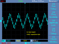
1) They have constant HF output frequency about 450 kHz and 0.5V
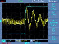
2) when loaded capacitively, they oscillate at about 50kHz (attached)
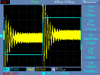
3) output impedance for step is awkward (attached)
But you spoke about amp with SMPS first, Hypex is class D PWM.
Attachments
Yes. All depend of the way you build / shield your amp. And filter your rails.
It would be useful to note simple DIY mods to some of the cheap Asian SMPS's to make them better.
What I was commenting on is that EVEN Hypex modules can scatter significant amounts of RFI, so cheaper supplies will probably be as bad or worse in this respect.
FCC should have banned them, there is no excuse for radiating EMC that bad, bad layout and bad choice of cable lengths are main culprits for SMPS noise and the bad press they get. If they radiate then in a case they are going to affect the circuitry they power, this is bad.
Yes, I saved it from the bin, along with a few other things. The trick is you stash them in your office and see if they get on the gone missing/needs cal list.
The top one AP High Performance Audio Analyzer & Audio Test Instruments : Accessories
Sounds like the Dutch Air Force
What I was commenting on is that EVEN Hypex modules can scatter significant amounts of RFI, so cheaper supplies will probably be as bad or worse in this respect.
John how did you measure that RFI, or do you mean RF noise on the output of the DUT?
The latter is, in an overwhelming number of cases, either CM or a result of grounding issues between all the test equipment and DUT(s). Issues often hardly noticed with docile analog stuff.
Jan
FCC should have banned them, there is no excuse for radiating EMC that bad, bad layout and bad choice of cable lengths are main culprits for SMPS noise and the bad press they get. If they radiate then in a case they are going to affect the circuitry they power, this is bad.
Who says they don't meet FCC? I understand that nCore for instance meets European standards (which should meet or exceed FCC) by a 20dB margin!
Jan
Hypex sell several SMPS as well as their Class D N'core.1)1) They have constant HF output frequency about 450 kHz and 0.5V
2) when loaded capacitively, they oscillate at about 50kHz (attached)
3) output impedance for step is awkward (attached)
But you spoke about amp with SMPS first, Hypex is class D PWM.
The measurements your referred were for Their Class D AMPs, i suppose ? Not their SMPS ?
I see no 450 KHz in their SMPS. And, by definition, they are loaded capacitively ;-)
The problem is most of them are regulated.It would be useful to note simple DIY mods to some of the cheap Asian SMPS's to make them better.
Last edited:
- Status
- Not open for further replies.
- Home
- Member Areas
- The Lounge
- John Curl's Blowtorch preamplifier part II