You mean picture in post 3430? Try please to draw it for both channels and common PSU, and with cables to signal source . You cannot simply to disconect input (signal gnd) from power gnd, output is defined referenced to power gnd, here must be direct connection or via this 10R. Other way input is floating, DC undefined..If you wire the amplifier up like I proposed with my drawing
Last edited:
I was sure jarkaa used ground breaker diodes (or a bridge) in // with the 10 Ohms for the chassis. Yes 10 Ohms is too litle. I would go for something like 1K, just to fix a reference when nothing connected (no current). Diodes are safe enough because they limit the voltage of the ground from earth to 0.7V, whatever happens. No need to the diodes to be high voltage because one is passing (0.7V) when the other is in reverse).TOn one amp I needed to remove the 10R resistor to kill the hum. It uses an inexpensive 30A bridge and mounts easily to the case.
Did-you mean just the parasitic added capacitance of the cable in the input is able to make your amp oscillating ?Just a cable is enough for initiating the hum.
Did-you tried to set a serial resistance (1K) in the input plug ?
You mean picture in post 3430? Try please to draw it for both channels and common PSU, and with cables to signal source . You cannot simply to disconect input (signal gnd) from power gnd, output is defined referenced to power gnd, here must be direct connection or via this 10R. Other way input is floating, DC undefined..
That is for two channels and a common PSU. It is not floating. It is referenced back to the 'T' taken from the main filter caps. This was the issue I had with jarkaa's second idea. If in that idea the interconnects weren't connected and the phono shields were isolated from the chassis then they would be floating and that causes amplifiers to explode.
The only thing the diagram doesn't show is the signal leads going into the amplifier. However if you do connect signal leads, the only way a ground loop can flow is down the signal interconnect shield from the source to the power amp, then down the wire labelled 'take one piece of wire from the ground junction...', to the filter caps, then down the safety earth and back into the signal source. If you've got a ground loop breaker between the safety earth and the star point then there's no loop.
The important thing for this set up to work well is for all the input connectors to really be mounted close together with the grounds on them all soldered together. You then take one wire from this point back to the quality earth T from the filter caps. Jarkaa has the phonos mounted at opposite ends of the case, which is sub optimal, nevertheless it should still work.
And AC and HF currents flowing through PSU capacity, primary /secondary? Here is always some current flowing through signal cable shield with unbalanced connection. And voltage drop at this shield resistance is than added to signal and amplified with amplifier gain.If you've got a ground loop breaker between the safety earth and the star point then there's no loop.
If you use this 10R to isolate input ground, you create from power amp something like diferential amplifier, all this disturbing voltage is across this 10R as common input voltage. And than this disturbing voltage is effective decreased.
Last edited:
Did-you mean just the parasitic added capacitance of the cable in the input is able to make your amp oscillating ?
Did-you tried to set a serial resistance (1K) in the input plug ?
Hello Esperado,
This is exactly how it behaves.
To your second question the answer is yes. This was the first thing I did.
Does it help to increase the series resistance?
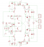
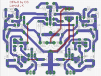
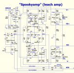
Attached schema and layout to clarify the situation. The safety diodes in parallel with feedback caps are not installed on the pcb.
J
Attachments
You can try this:
- Plug your cable in the inputs.
- Remove C12.
- Tune C1 & C18 to have no oscillation and a flat bandwidth at HF (no peak in the response curve).
- Plug-in a square wave generator @ 50Khz to your cable.
- Replace C12 and tune it to have no peak in the square waves.
This will be you minimal C12 value, that you can increase for best listening results.
Last edited:
Perfectly resumed, ColinThe lpf should only be used to prevent the amplifier from slew Induced issues.
")
Actually, Julia is a good one. Even used by professionals for recording / mixing / mastering. Despite the fact that it was introduced to the market 10 years ago, it is still supported by the manufacturer - drivers are Windows 7/8 compatible. It utilizes high quality AD / DA converters, so for measurement purposes - I think it would be a good choice. ASIO interface is supported. 100 euros is a good price. Make sure you've got an old-style PCI slot on your motherboard - the card was invented before PCI-e became mature.
Is ESI julia well suited as waveform generator to achieve wavesquare test? I have have a analogic philipps 2x50mHz scope but no function generator.
Marc
Is ESI julia well suited as waveform generator to achieve wavesquare test? I have have a analogic philipps 2x50mHz scope but no function generator.
Marc
I don't like the way my sound card (e-mu 1616m) forms the square wave - by some reason I always see some "ringing" right at the output of the card. I'm afraid, julia may have the same issue, though I don't know for sure.
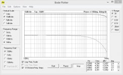
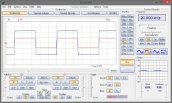
I use a USB-PC SCOPE + GENERATOR (2CH.) Velleman PCSGU250 as a function generator - this one forms a pretty good square vave and rather versatile tool in general - for example, it can create Bode plots automatically, showing both amplitude and phase responses at one plot (see attached examples).
Cheers,
Valery
Attachments
Last edited:
I don't like the way my sound card (e-mu 1616m) forms the square wave - by some reason I always see some "ringing" right at the output of the card. I'm afraid, julia may have the same issue, though I don't know for sure.
I use a USB-PC SCOPE + GENERATOR (2CH.) Velleman PCSGU250 as a function generator - this one forms a pretty good square vave and rather versatile tool in general - for example, it can create Bode plots automatically, showing both amplitude and phase responses at one plot.
Cheers,
Valery
Thanks for reply Valery, i think i have to found a function generator than.
Marc
You can try this:
- Plug your cable in the inputs.
- Remove C12.
- Tune C1 & C18 to have no oscillation and a flat bandwidth at HF (no peak in the response curve).
- Plug-in a square wave generator @ 50Khz to your cable.
- Replace C12 and tune it to have no peak in the square waves.
This will be you minimal C12 value, that you can increase for best listening results.
Hi,
Thanks for the advice! I think i Will use trimmer caps to tune the compensation.
I am currently moving to countryside and There Will be Few days of delay in Electronics.
J
I have been using this Chung instruments 555RC oscillator. It seems to work well. Only drawback is that it doesn't have a power light so it's easy to forget to shut it off resulting in a lot of battery changes. It puts out a nice crisp square wave.
Advise for mounting
If I separate the heat sink of 2 driver transistors, and mount one VBE multiplier transistor on the same heat sink of the one transistor driver, do quiescent current stable?
If I use cable to connect the output transistor (NJW0281G and NJW0302G), how long cable that I can use?
If I separate the heat sink of 2 driver transistors, and mount one VBE multiplier transistor on the same heat sink of the one transistor driver, do quiescent current stable?
If I use cable to connect the output transistor (NJW0281G and NJW0302G), how long cable that I can use?
If I separate the heat sink of 2 driver transistors, and mount one VBE multiplier transistor on the same heat sink of the one transistor driver, do quiescent current stable?
If I use cable to connect the output transistor (NJW0281G and NJW0302G), how long cable that I can use?
Hi Bimo, yes, quiescent current will stabilize, assuming that in a normally operating circuit those drivers heat-up in a similar way, so you can track any single one of them.
Output transistors - it is important that the wires, connecting their collectors and emitters to PSU and output sockets are as "fat" and as short as possible. The base wires, obviously going to PCB, may be thinner and longer, however I would consider 25cm (~ 10 inches) as a practical maximum...
Cheers,
Valery
I was playing the Slewmonster today with the Spooky IPS ad I noticed that the heatsink on the VAS of the IPS is running pretty hot. I can hold onto it but it is hot. Where should I measure to make sure the bias on the IPS is set properly? Which resistors do I measure and what voltage should I be looking for.
Thanks, Terry
Thanks, Terry
Attachments
Terry, measure the voltage over R25 (voltage over R31 will be the same or very close to it - you can check).
The current will be ([voltage over R25] / R25). It has to be 7.5mA, as per OS's design.
Out of these 7.5 mA, 3mA go to the LEDs and 4.5mA go to VAS.
Current through the LEDs ir relatively constant (3mA), so you can always calculate the VAS current as ([current through R25] - 3mA).
In fact, transistors getting hot are cascodes Q12, Q13.
Cheers,
Valery
Hi Valery,
Thanks for the detailed explanation. That is exactly what I did so I guess the VAS is just meant to run that hot. I measured R26 and it figured at 4.5mA so I guess it's right. Q12 & Q13 just seem a little too hot. The amp actually plays beautifully.
Thanks again, Terry
Thanks for the detailed explanation. That is exactly what I did so I guess the VAS is just meant to run that hot. I measured R26 and it figured at 4.5mA so I guess it's right. Q12 & Q13 just seem a little too hot. The amp actually plays beautifully.
Thanks again, Terry
- Home
- Amplifiers
- Solid State
- Slewmaster - CFA vs. VFA "Rumble"