You can to see in RMAA how it influence on amplifier's output with closed input. I don't remember level of pulsing AC of my power supply (because it was 1,5 years ago), but diagram has been saved.My first amp was a ZENv3 and I had to resort to a cap multiplier. It did have an impact on the sound - which I wasn't that keen on either.
However I had already read Nelson Passes advice and have built the power supply with the bigger cap after the capacitance Multiplier.
Tthe configuration is 5,000uf>cap Multiplier>64,000uF. The ripple at the 500ouf is about 0.6V and at the 64000uF its down to 15mV.
64000uF at the output should dominate the response all the way down to a few 10's of hertz so I am anticipating that the cap multipler will largely be out of the picture sonics wise. The power transformer is something like 240VA so I do not anticipate it sagging significantly even under sever peaks.
Shoog
")
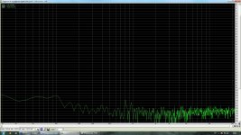
On diagram: Jean Hiraga's Super Class A 30W made for "rear" (0,18F, bias 0,9A, gain=21, toroidal transformer 2*18V*4,4A 160W, BJT: 2sc1775+2sa872, MJE15034+MJE15035, MJL21196+MJL21195) average self noises with closed input. I have made it on my own PCB.
Attachments
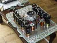
Built out my first channel and it worked first time. Hooked it up to a 3W test speaker and can't here any hum and it sounds very decent for a first try. Standing current was originally .37A which I increased to 1.27A, may knock it back to the intended 0.8A - but seems as if everything is coping admirably running at the hotter setting. Will build the second channel over the next few days and hopefully will have a working amp by the weekend.
Shoog
Shoog
Member
Joined 2009
Paid Member
Built out my first channel and it worked first time. Hooked it up to a 3W test speaker and can't here any hum and it sounds very decent for a first try. Standing current was originally .37A which I increased to 1.27A, may knock it back to the intended 0.8A - but seems as if everything is coping admirably running at the hotter setting. Will build the second channel over the next few days and hopefully will have a working amp by the weekend.
Shoog
Photo in studio!
I must agree that I've tried a cap multiplier too and wasn't too impresssed with it either.
It's OK if you are starting out and want to experiment and save a few pennies but ultimately the BRUTE FORCE power supply will always be better.
My 100W/Ch Pass Aleph 4 has a monster power supply to keep its Class A hunger buds happy.
It's OK if you are starting out and want to experiment and save a few pennies but ultimately the BRUTE FORCE power supply will always be better.
My 100W/Ch Pass Aleph 4 has a monster power supply to keep its Class A hunger buds happy.
Attachments
Last edited:
Built out my first channel and it worked first time. Hooked it up to a 3W test speaker and can't here any hum and it sounds very decent for a first try. Standing current was originally .37A which I increased to 1.27A, may knock it back to the intended 0.8A - but seems as if everything is coping admirably running at the hotter setting. Will build the second channel over the next few days and hopefully will have a working amp by the weekend.
Shoog
I bought resistors 0.1% 15 ppm.
Attachments
I have a bit of a strange measurement going on here. I have the front end rigged up on the bench and powered up. I have 660R as the collector loads and I am measuring just 1.09mA through them. Spice simulations point to about 4.5mA as been the target. This suggests that the front end would be current limiting for the output stage.
Any ideas.
Shoog
Any ideas.
Shoog
I have a bit of a strange measurement going on here. I have the front end rigged up on the bench and powered up. I have 660R as the collector loads and I am measuring just 1.09mA through them. Spice simulations point to about 4.5mA as been the target. This suggests that the front end would be current limiting for the output stage.
Any ideas.
Shoog
I don't believe to simulators (multisim, microcap and other)
I don't believe to simulators (multisim, microcap and other)
I tend not to either as the models rarely match the real devices. However its a good place to get to the right ball park component values.
The question is what experience are people having in biasing up their Jfets. I am using the 100R trimmer at the junction, do i need to reduce this value to get the front end to push some more current. Ideally I am looking to pass the 4.5mA such that the front end stays 100% in class A. There seems little point in building a class A output stage and then driving it with a class AB driver.
It seems that with modern 2SJ74's and 2SK170's they need just 0.1v of bias to conduct 4mA and the Nelson Pass F5 is using just 10R for biasing, equivalent to replacing the 100R trimmer with a 20R trimmer.
Shoog
Last edited:
170+74 had discontinued. 2SK246Y+2SJ103Y as alternative with Idss=1.2-1.5 mA.I tend not to either as the models rarely match the real devices. However its a good place to get to the right ball park component values.
The question is what experience are people having in biasing up their Jfets. I am using the 100R trimmer at the junction, do i need to reduce this value to get the front end to push some more current. Ideally I am looking to pass the 4.5mA such that the front end stays 100% in class A. There seems little point in building a class A output stage and then driving it with a class AB driver.
It seems that with modern 2SJ74's and 2SK170's they need just 0.1v of bias to conduct 4mA and the Nelson Pass F5 is using just 10R for biasing, equivalent to replacing the 100R trimmer with a 20R trimmer.
Shoog
Built out the second channel. fired her up and she is drawing 1.65A for the same settings as the first channel. Cracking up at very low volumes so there is definitely a serious issue. Will do a detailed check over my wiring - early indication is its on the positive side. Maybe a toasted transistor - hopefully not the K74 as I only have the one.
Shoog
Shoog
Built out the second channel. fired her up and she is drawing 1.65A for the same settings as the first channel. Cracking up at very low volumes so there is definitely a serious issue. Will do a detailed check over my wiring - early indication is its on the positive side. Maybe a toasted transistor - hopefully not the K74 as I only have the one.
Shoog
My test version had super stable bias, bias didn't changing in time of using (7-8 hours with open and closed input).
What transistors you are using?..
Got both channels working last night (though one channel is a bit dicky). Solder/track frass was causing the crisis in the second channel. Will be examing the boards for imperfections today. One channel now has bias of 0.35A and the other 0.5A. Will be spending the day adjusting the standing bias to get them both to 0.8A, I am a little surprised at how different they are since the transistors are reasonably well matched.
Shoog
Shoog
Got both channels working last night (though one channel is a bit dicky). Solder/track frass was causing the crisis in the second channel. Will be examing the boards for imperfections today. One channel now has bias of 0.35A and the other 0.5A. Will be spending the day adjusting the standing bias to get them both to 0.8A, I am a little surprised at how different they are since the transistors are reasonably well matched.
Shoog
It's not anomaly - it's usual practice for Le Monstre
Last edited:
Got both channels working last night (though one channel is a bit dicky). Solder/track frass was causing the crisis in the second channel. Will be examing the boards for imperfections today. One channel now has bias of 0.35A and the other 0.5A. Will be spending the day adjusting the standing bias to get them both to 0.8A, I am a little surprised at how different they are since the transistors are reasonably well matched.
Shoog
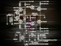
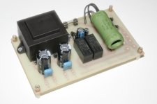
Soft Start for Le Monstre, 56 om 25W, 2 seconds (will be 4 seconds) delay and DC Protection for Super Class A 30W
Attachments
Why do you want 4 secs delay? 100mS is usually sufficient.
Because will be 1,5F filter with small diodes 40EPF06
100 mS are small delay, 500 mS - 1 S usually using. (but it is lyrics
)Good to hear that the bias difference isn't unusual.
I have two solid state relays with their own built in driver circuits so will be building a DC protection circuit for the outputs. My speakers are vintage german field coil with extreme sensitivity - I would not be happy if this baby took them out.
Shoog
I have two solid state relays with their own built in driver circuits so will be building a DC protection circuit for the outputs. My speakers are vintage german field coil with extreme sensitivity - I would not be happy if this baby took them out.
Shoog
Got both channels working perfectly. Biased at 0.98A. Put trimmers in one channel to allow both channels to be matched perfectly. Offset less than 15mV and sounding damn fine on my test speakers.
Heatsinks are staying at room temperature after a short run time
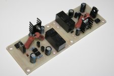
Will post some photo's later when I get a chance.
Final build out and test in the main system hopefully by Sunday.
Shoog
Heatsinks are staying at room temperature after a short run time
Will post some photo's later when I get a chance.
Final build out and test in the main system hopefully by Sunday.
Shoog
- Home
- Amplifiers
- Solid State
- Hiraga "Le Monstre"