Below is my original post, the gain resistor goes between the FET sources. Use PMA's resistor values since he fixed the limited common mode range in the original. If you can imagine the original (Demrow paper above) where the first two op-amps are repurposed as one for common mode elimination and one as differential gain you can place the 4 resistors around the output amp right at the input and eliminate the third op-amp. As a bonus you get a single ended output and reuse two of the common mode resistors as your gain setting network.
...
Scott,
Can you give some idea of the about the expected en noise performance of this circuit as drawn?
PMA,
Can you share your choice for U1?
Thanks,
Dave
We have been too polite to refer to 'audio Nazis' '-)
For too long!
No, I want to go back even further.
Someone complained that the Electrocompaniet OTALA power amp was not 100% made of cheap parts, and they are partially right.
What appears to happen here is exactly what happened to me in 1968, when I developed my version of the complementary differential input stage. I worked for Ampex, so I used complementary dual pairs of transistors, that were supplied to the Video division primarily, but available from 'stores'. They, too, were expensive, but 'free' to me.
Matti and Jan apparently went into 'stores' at Phillips Research and found some matched dual pairs. This is what they apparently put into their prototype, and the Electrocompaniet guys, being VERY junior in design, at the time, just used them, rather than making roughly equivalent matched pairs from individual devices. YET, the Otala amp, (that I have working in my lab), is one of the best designs that I ever came across in its power range, even to this day. Yet, almost every part is almost 'stock' and the 'difference' is in how they are put together.
I did, but not complaining, just pointing out that somehow we always seem to need some moreexpensive part.
In Otala's case, everything but the two dual BJTs cost less than DM 30 (in theme teher dark days, it was Deutsche Mark), and just those two cost DM 56, or 86% more than the lot.
That said, I have heard some samples of it made with hand matched BC550B trannies, which are ridiculously cheap, some 3-4 Euro cent par unit, and they did a good job of it.
The other point are the output devices, BD 203 and 204. By now, they are damn hard to find, over time they have been replaced by newer devices. For some time, I have been wondering how it would sound if I replaced them with say BD 249/250 C. This is a nex of kin relative of TI's TIP 35/36, and from TI's Power Semiconductor book, the only difference seesm to be Ton, Tstore and Toff, in all cases the BD type is clearly superior.
However, the BD 249/250 C can swing 100V (Otala's 60V), can deliver 25 A continuously (Otala's 7A, if memory serves) and 40A peak (!!!), etc. Otala's were rated at 60W, these are rated at 125W. That would permit us to expand on Otala's rating, from 25/50W into 8/4 Ohms to 25/50/100W into 8/4/2 Ohms.
I believe the BD 249/250 C to be the unsung heroes of audio. Each and every time I replaced any transistor with them, I got a better sound, sometimes more, sometimes less, but always better. They have a way of sounding smooth and effortless. Their only failing is their low voltage rating, because despite the book stating there are D (120V) and E (140V) versions, I have never actually seen any offered by anybody.
John is right, methinks, it's time to revisit the Otala amp. I have no idea what demon possessed me to sell my sample, but that was a bad mistake.
No, it was designed in the early 70's at Phillips Research by Matti Otala and Jan Lostroh. There is an AES paper describing it completely. The amp was copied by Electrocompaniet in Norway, and is usually called the 'Otala' amp. It was a revolution in amp design.
Er, um, John? Actually, Per Abrahamsen of Electrocompaniet bought the rights to manufacture it. Check with Matti, BUT, if memory serves, their version was a bit different.
Still caused a big stir in its day.
Jan thanks.
I can’t find the design doc that is mentioned in Fig.3
(Page not found | Linear Audio NL.)
See also this old post from jcarr
George
Was this "Otala amp " a HK product ...?
Perhaps it would be more accurate to say that H/K amps became Otala's amps. John will know this better, but I remember H/Km hired Otala in a jiffy. So, from the mid-70ies top the early 80-ies, Otala worked for H/K and provided the basis to everything they have made ever since.
If memory serves, H/K's models like 505 were the first to employ the combination of wide bandwidth and low NFB, and their underlying topology is still used to this day, albeit greatly updated. Even in their Citation series.
Again, if memory serves, it was an easy and natural step for H/K, I seem to have read somewere that the late Bernard Kardon was also very much a wide bandwidth man.
Last edited:
Jan, MANY THANKS for the link, you just made my week.
I had always wondered why the amp had always been mentioned as Otala's, when the original text printed in IEEE mentiond two authors. Always wanted to hear from the other author, and finally, after so many years, I can.
+1000
Jan thanks.
I can’t find the design doc that is mentioned in Fig.3
(http://www.linearaudio.nl/Miscellaneous/lohstroh pp.pdf.)
See also this old post from jcarr
George
Actually it is here: http://www.linearaudio.nl/linearaudio.nl/images/pdf/otala low tim amp.pdf .
I will fix the other link.
jan
Actually it is here:
Obliged!
Terje Sandstrom used to have this site http://home.online.no/~tsandstr/AudioStartsHere.htm which contained information from his former (audio) life. The link is broken, if someone can trace a valid path, it will be nice.
Wavebourn had contributed in a ru site a response from Jan Lohstroh.It is identical to Jan’s interview
ÃÓ-50 â "Ïðèáîé"
“By accident I did find this website and this thread. Amazing to see that 37 years after the moment that I designed the 25W amplifier, taking recommendations of Matti Otala into account, this amplifier is still being discussed. Also interesting to read that this amplifier is now referred to as the “Otala amplifier”. The story behind the amplifier is the following. I started in 1970, fresh from university (Technical Physics at Delft Technical University; thesis on analogue circuitry for Nuclear Magnetic Resonance measurement equipment), as a young researcher in the digital memories group of Philips Research in Eindhoven, The Netherlands. In 1972 we had a working guest from Finland, prof. Matti Otala from Finland, who wished to spend a sabbatical year in Philips Research. Matti became a member of a subgroup working on a magnetic bubble memory system; I was at that time member of subgroup working a holographic optical memory system. It was once during lunchtime that I told Matti Otala that I planned to design and build a solid state audio amplifier for myself, because my wife did not like the large form factor of my tube audio amplifier any more that I built as a student some five years before (own design). Matti then told me that he had done some research on audio amplifiers in Finland and explained to me his TIM theory. He recommended me to build something with a low open loop gain, a high open loop bandwidth, with low feedback and a high slew rate. Preferably class AB with a switch point to class B for loud passages and peaks only. He also recommended not bothering about the total harmonic distortion because as a number, without details about how cleanly the signal crosses the zero line, it would not really determine the sound quality if the value is not too high. I was intrigued by his recommendations. I had seen some schematics with a single power supply and a non-symmetrical output (with a big bootstrap capacitor), which I did not like at all. In my view a clean good sounding design should be as symmetrical as possible, using a double power supply, avoiding capacitors (so DC coupled) and a full symmetrical output stage using npn and pnp transistors. I drew up the circuit diagram that is almost the same that you know from the publication and showed that to Matti. He thought that this approach could indeed eliminate the TIM problem and that it would be very worthwhile to build it. He had some comments about the feedback circuitry and RF damping in the power supply lines that I did take into account. In fact he was very enthusiastic and eager to see the measuring results of this design and said that if they were good we could publish it. The problem was that I did not have a labfacility at home. So Matti and I launched the idea to do the work in Philips time, using Philips Research measuring equipment from an audio group in Philips Research. We went together to our department manager and asked him whether it was possible that we deviated from the work we were supposed to do, for a two weeks project that could result in an interesting publication, although not on digital memories. We were happy that he said yes. We selected the best transistors with the highest Ft’s that were that time available from the catalogue of Philips Semiconductors and did build the circuit as a mono amplifier, using two laboratory power supply units and a big heat sink for the output transistors. We only had to tweak some resistor values to make the circuit working well and the measuring results were immediately quite impressive. We did some listening test with a high quality Philips oudspeaker in the anechoic room of the audio group using a high quality turntable with some high quality mono records. We were impressed by the clarity of the sound, the high dynamic range, and the fact that the clarity remained very pleasant even after listening for more than an hour to the music. We did not do any specific TIM testing, because we did not have a measuring set up for this and the time allowed to work on the project was almost over. However from our listening experience we were sure that if there was any TIM distortion, it would be very low in this amplifier. We gave a presentation to the development group of the audio business group of Philips Consumer Electronics. They were impressed but not interested to take our approach into account because Philips at that time was only interested in the low end business; Marantz was not yet part of Philips. So without interest of the Philips audio business and without any possibility to apply for a patent for this circuit, being built-up of discrete components, we decided to publish it as originally anticipated. Soon there was an AES convention in Feb. 1973 in Rotterdam in the Netherlands that accepted our paper. As Matti spoke better English than I at that time, we agreed that he would present the paper, also because questions about TIM could be better answered by him. Later we submitted the paper to the IEEE journal where it was accepted as well. The rest of the story you know. Electrocompaniet adopted the design for their first product and even sold it initially under the name OTALA-LOHSTROH amplifier (see: http://www.avl-audio.ru/_mod_files/ce_images/Electrocompaniet/25wfront-2.jpg). When we discovered this, Matti and I let them stop using our names because their design was not authorized by us. In my professional career, while in research, I concentrated on integrated digital circuitry and memories. I published many articles about these topics and was (co)inventor of 22 patents, before I became a manager (successively in Philips Research, Philips Semiconductors, Philips Consumer Electronics and Philips Intellectual Properties & Standards up to the level of divisional Senior Vice President). I did not take the time to follow the literature on audio amplifiers until recently. I was simply too busy in my job, and spending my private time on mountaineering and music (playing the piano). At the age of 60 my contract with Philips expired. Then I started my own consultancy firm: “Lohstroh Consultancy” on R&D Management, Intellectual Property and Standardization. One of my current jobs is a part time job in ARTEMISIA, to be their Secretary General (see: https://www.artemisia-association.org/artemisia_secretary_general ). I had over the years only a few contacts with Matti by e-mail and only saw him three times since 1973. The last time at the IFA Consumer Electronics Fair in Berlin in a Electrocompaniet booth some 10 years ago. Apparently he was acting as an advisor for them. The last e-mail contact with him was two years ago. He was then suffering from a brain disease and was hardly able to speak and type. Shortly after I had the last e-mail contact with him a burglar did steel all computers from my home, so I lost all data and e-mail addresses. A contact that I know in Finland which knows Matti, confirmed me todya that Matti is still alive, but bound to a wheelchair.
Regards, Jan Lohstroh “
George
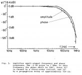
What causes this “150ns propagation delay” ? (pages 11, 17, 21)
http://www.linearaudio.nl/linearaudio.nl/images/pdf/otala%20low%20tim%20amp.pdf
George
http://www.linearaudio.nl/linearaudio.nl/images/pdf/otala%20low%20tim%20amp.pdf
George
Thanks Jan.
(The piano and I were born in the same year.
") I need renovation too!
I need renovation too!Back in the 1970s-80s there was a second hand audio dealer in London called Dennis Trickett who always reckoned that the early Electrocompaniet Amp was the best sounding solid state amp available in the mid 80s! [I bought from him a brand new Precision Fidelity pre, an early Brauer PU arm and all sorts of rare bits and pieces, including broken SPU cartridges which the importer would back then replace with factory rebuilds for £30. Dennis also rebuilt Quad, Leak and any other tube amp to the highest quality………I would have loved for him to build a top quality Tube amp from scratch….but he died very young from a very fast spreading cancer].
What causes this “150ns propagation delay” ? (pages 11, 17, 21)
http://www.linearaudio.nl/linearaudio.nl/images/pdf/otala%20low%20tim%20amp.pdf
George
You need the phase vs. frequency plot. IMHO this is an old school way of looking at excess phase, lumping it as a prop-delay. There is no way this amplifier has no higher order poles at all.
You need the phase vs. frequency plot. IMHO this is an old school way of looking at excess phase, lumping it as a prop-delay. There is no way this amplifier has no higher order poles at all.
I have not met again a prop delay expression in an amplifier ‘phase vs freq’ diagram.
Fig.3 is such a diagram.
The fig description makes clear that LP filter and prop delay are two different contributors (acc. to the authors).
George
Attachments
Last edited:
I have not met again a prop delay expression in an amplifier ‘phase vs freq’ diagram.
Fig.3 is such a diagram.
The fig description makes clear that LP filter and prop delay are two different contributors.
George
You need a linear with frequency plot that goes out much higher in frequency. In the very least the low ft devices of the day would have base charge storage that would contribute phase in a distributed fashion. Let's just say IMO the author's simplification is naïve.
Last edited:
Scott, I don’t disagree on what you say in both of your posts, especially with the “base charge storage that would contribute phase in a distributed fashion”.
But then look at their Fig. 8. Phase compensation is distinct from the fixed -frequency independent- delay compensation element.
I would say they didn’t try a simplification here. I suspect a fundamental disagreement around the ‘f word’ (their page 6 'i' para ?).
George
But then look at their Fig. 8. Phase compensation is distinct from the fixed -frequency independent- delay compensation element.
I would say they didn’t try a simplification here. I suspect a fundamental disagreement around the ‘f word’ (their page 6 'i' para ?).
George
Er, um, John? Actually, Per Abrahamsen of Electrocompaniet bought the rights to manufacture it. Check with Matti, BUT, if memory serves, their version was a bit different.
Still caused a big stir in its day.
I had one in the 70s, and it was pretty good, just not like a good tube amp.
It did shut down thermally on less efficient speakers, though.
Perhaps it would be more accurate to say that H/K amps became Otala's amps. John will know this better, but I remember H/Km hired Otala in a jiffy. So, from the mid-70ies top the early 80-ies, Otala worked for H/K and provided the basis to everything they have made ever since.
If memory serves, H/K's models like 505 were the first to employ the combination of wide bandwidth and low NFB, and their underlying topology is still used to this day, albeit greatly updated. Even in their Citation series.
Again, if memory serves, it was an easy and natural step for H/K, I seem to have read somewere that the late Bernard Kardon was also very much a wide bandwidth man.
[SIZE=+2]Harman Kardon Citation II Amplifier[/SIZE]
This 70 pound chocolate colored behemoth, designed by Stewart Hegeman is quite a feat of engineering. It's impressive weight and construction is equally matched by the impressive looking line of tubes, and the conservative 60 WPC power rating. But the really impressive work is "under the hood". Hegeman felt that a good amplifier should not be bandwidth limited to the audible range, but should extend farther in both extremes, so the amplifier can handle the audible range without any of the artifacts of limited bandwidth amplifiers; such as phase shift at the frequency extremes.
You need a linear with frequency plot that goes out much higher in frequency. In the very least the low ft devices of the day would have base charge storage that would contribute phase in a distributed fashion. Let's just say IMO the author's simplification is naïve.
If memory serves, the output devices were quite fast for the day (they are relatively medium power, not the sluggish 2N3055-type high power devices). That's why there are 2 pairs for just 50W Pout.
I think they were 30MHz Ft devices.
jan
I got the first prototype OTALA amp in 1975 or so, when I was in Switzerland. The guys, Per and his buddy, visited me after an AES and I JUST had to have it! It was the only 'commercial' amp that did not annoy me when I used the STAX electrostatic headphones. They, at first, declined, saying that it was registered at the border and had to pass back through. So I gave them a blown up Quatre amp to use instead, and a pile of money, and they accepted. I really appreciate their doing this for me, to this day. I used this amp, off and on for decades. In between, I used tube amps, but in the end, I always returned to the OTALA. At the time of the firestorm, in 1991, I had the OTALA driving a pair of WATT-Puppies, with a JC-80, on a Linn table with a Breuer tonearm (the best I have ever had), and of course, I lost them all. The only thing that I have not been able to replace adequately is the Breuer arm.
I use a replacement OTALA amp now in my office, and for the price, it was a BARGAIN!
On re-reading Jan Lohstroh's comments, I would like to say that he does deserve more credit. But, without Matti's input, the design would not have gotten very far. In the USA, we had already moved on to more sophisticated topologies like the complementary differential input stage.
What really made the difference was the high slew rate and the high quiescent current of the output stage, which I increased even further to get even lower distortion, although it ran a bit warm. This design was a real breakthrough in amp design philosophy, and I still try to use it today to the best of what is practical.
- Status
- Not open for further replies.
- Home
- Member Areas
- The Lounge
- John Curl's Blowtorch preamplifier part II