Hi,
I'm facing with a problem of "shouty Vocal" or "too much Mid-frequency" on my 2-way speaker. I strongly believed that there's spike at 450Hz to 800Hz and its peak at about 650Hz. Now I'm looking to tame the annoying mid-frequency by "parallel notch filter" but I've never seen anyone did it - mid-frequency - with this method before. And seeing the suggestions from any online calculators made me very confused because they told me to use too much large value on components such as 47uF of capacitor. O.O
So, I want to ask : Do I go the true way ? I mean Is a parallel notch filter suit for my solution ? If there's another methods to suggest, please tell me.
Thank you
Last edited:
Seeing www.troelsgravesen.dk, I observed the designer seems to prefer a "series" notch filter than a "parallel" notch in almost of his projects even used with a woofer. Why ? Is it interesting for me to use a series notch filter instead of a parallel notch ?
After trying to fill the frequency value where it's "peak" instead a resonance frequency(fs) in the series notch online calculator, I found the value of components in series notch filter looks (in my opinion) more reliable than those from a parallel notch filter - not too large, not too small.
What do you think about it ?
Last edited:
I think Troels' approach looks promising, though I haven't tried it.
6" bass comes out a bit vocal shouty as you observe with say, 1.8mH coil.
He says it's a problem with narrow baffles and small drivers.
Really don't want to go 2.2mH or 2.5mH, because that sounds dull and lifeless. I think advice depends on circumstances, but to get away with with about 1mH and a notch must be good. Parallel LCR or series? That depends on the exact modelling. Parallel will give you a higher impedance.
But what are the drivers and box dimensions? That's what it's really all about.")
6" bass comes out a bit vocal shouty as you observe with say, 1.8mH coil.
He says it's a problem with narrow baffles and small drivers.
Really don't want to go 2.2mH or 2.5mH, because that sounds dull and lifeless. I think advice depends on circumstances, but to get away with with about 1mH and a notch must be good. Parallel LCR or series? That depends on the exact modelling. Parallel will give you a higher impedance.
But what are the drivers and box dimensions? That's what it's really all about.
I think the large majority of questions can be answered with "Read this link first and come back with questions after"
Hi,
A parallel notch won't work and will blow up your amplifier.
http://audio.claub.net/Simple Loudspeaker Design ver2.pdf
FRD Consortium tools guide
http://web.archive.org/web/20090902124715/http://geocities.com/woove99/Spkrbldg/DesigningXO.htm
As ever proper x/o design is needed rather than stupid calculators.
rgds, sreten.
I do think that 5-6" bass on narrow baffle is really hard to get tonally right. They tend to brightness or harshness in the midrange, especially female vocal. Everything I hate about a speaker...
Troels does a ca. 600-800Hz series LCR notch very frequently. He obviously likes it. Impact on impedance is not too bad, but it takes it lower to around 4-5 ohms. The BBC used a parallel LCR notch or "Trap" a lot for slightly different reasons with polycones. It's much harder to model, but when it works, it works well.
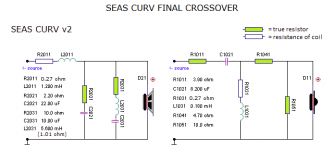
SEAS CURV
Troels does a ca. 600-800Hz series LCR notch very frequently. He obviously likes it. Impact on impedance is not too bad, but it takes it lower to around 4-5 ohms. The BBC used a parallel LCR notch or "Trap" a lot for slightly different reasons with polycones. It's much harder to model, but when it works, it works well.
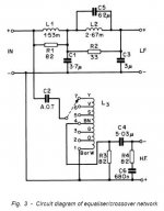
What is seen much too often is the crossover depicted above. Any driver mounted on a baffle will have an f3 = 11,600/width of baffle in cm, here 11,600/19 = 610 Hz, in short, we have a rising frequency response towards higher frequencies and this is usually dealt with by adding a large series inductor for the midbass in order to tame too much energy around 1 kHz. Problem is that by doing so we tilt the response so much we have a dip right in the middle of the midrange around 500 Hz, see figure below (green graph). Depending on the intrinsic response of the actual driver this may be more or less severe and a few times we can get away with the simple "v1" crossover.
SEAS CURV
Attachments
A series notch would blow up the amplifier, not a parallel notch.
Hi,
Clueless terminology. A parallel notch is a series LCR.
A series notch is a parallel LCR. Your simply wrong.
Series and parallel are relative to the driver.
rgds, sreten.
Last edited:
I have used both. If either had a chance to blow an amp I would guess it's the series notch as it is shunting the driver but it's used rather commonly as an impedance leveller so I'm not sure I understand what's being said here. Steve's post 9 has a series notch on the woofer in attachment 2.
I have used both. If either had a chance to blow an amp I would guess it's the series notch as it is shunting the driver but it's used rather commonly as an impedance leveller so I'm not sure I understand what's being said here. Steve's post 9 has a series notch on the woofer in attachment 2.
Hi,
Tweeter impedance compensation is a series LCR in parallel
with the driver. Its a parallel notch, not a series notch.
Parallel notches are series LCR, and series notches parallel LCR.
rgds, sreten.
Last edited:
I also vote for getting some cheap measurement gear instead of blindly buying crossover components that *might* solve it but probably not. It's not like midrange inductors are cheap so if you don't get it perfect the first guess you'll probably have spent in vain as much as a cheap microphone costs.
Then simulate a notch with some software or spend a little more money and get an analogue or digital DSP and just create an EQ notch. Much more simple and opens the doors for more fancy stuff =)
Then simulate a notch with some software or spend a little more money and get an analogue or digital DSP and just create an EQ notch. Much more simple and opens the doors for more fancy stuff =)
Series and parallel are relative to the driver.

We are talking 3 terminal ladder networks so series and shunt might be a little clearer, but yes it is relative to the driver (which is usually the final shunt element).
That is, a series location for a parallel tank, and a shunt location for a series resonant circuit. Clear as mud.
Note that a shunt conjugate doesn't "blow anything up" because it doesn't drop any lower than the driver impedance. Shunt notch filters of lower impedance may be okay as long as there is sufficinet circuit impedance in front of them.
David
Last edited:
Hi,
Is it dangerous for the amplifier to use more than one notch trap in fhz domain (//LCR in serie with the driver) by driver or in the whole filter (e.g. one in the mid like the op and one or two in the tweeter) ?
My understanding is the drivers will lake of life and power if the whole filter have too much coils and resistors but the impedance stay stable and will not blow the amp ?
In the mid, which peak can be heard ? + 3 db ? more ? Is it not for the OP some higher harmonic peaks as well ?
Very interresting, as DSP EQ become famous but always at the price maybe of some deterioration in relation to the DAC sound ?!
@ OP, I has a similar problem and with the advises of fellows I went to measurement. In second hans for less than 150 euros for gears, I measured a peak around 4000 and puted a short width trap notch in the tweeters : I never regreted it. You really have to measure in your listen room to visualize the peaks on a screen !
regards
Very interresting, as DSP EQ become famous but always at the price maybe of some deterioration in relation to the DAC sound ?!
Why would there be? It is getting more and more widely used because it is more simple and better =) As long as you have sufficient amount of bits of precision then any performance loss is insignificant. It is also far more precision than realistically achievable with analogue components.
The only area off the shelf DSP might not always work is in the low sub bass where you would need higher precision in the calculations, but we are talking about subsonic now.
The general rule is to avoid low impedance and high phase angle simultaneously. That is an amp killer.
Usually your notches will be protected by the bafflestep coil from going too low in impedance.
We started by saying midrange on small drivers is tricky to get flat, though sreten seems to think it is easy. But this lively reed cone SEAS ER18RNX also has a 5kHz peak that might be problematic:
H1456-08 ER18RNX
Hard to say if that is dustcap or cone breakup or both. But the deader polycone SEAS U18RNX/P looks like it won't need a shunt LCR notch around 5uF/0.2mH/1.5R.
H1571-08 U18RNX/P
It's always interesting to study Troels' designs. He tends not to use notches much, except for a RC tank across the bafflestep coil. I have to admit I like notches less and less these days. Too fussy. Better to choose well-behaved drivers IMO.
- Status
- This old topic is closed. If you want to reopen this topic, contact a moderator using the "Report Post" button.
- Home
- Loudspeakers
- Multi-Way
- Notch filter for midrange ???