Series and parallel are relative to the driver.
This is incorrect.
A series network has the filter components in series and the network is parallel to the driver.
A parallel network has the filter components in parallel and are in series with the driver.
I found that a parallel LCR in series with the bass driver was very effective at removing my baffle step related hump (though mine is a bit higher in frequency than the OP's). I actually have two parallel LCR's in series with the midbass unit. One tuned to about 1.4Khz to deal with the baffle step hump and the other tuned to around 4Khz to deal with driver breakup. The lower one is fairly low Q and the higher one a bit higher Q.
No problems so far with the amp, and to my ears (and anyone who has heard them so far) they are very natural sounding.
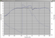
Attached shows the difference in the response with and without the 1.4Khz // LCR ( Blue is without in case it wasn't obvious") ).
).
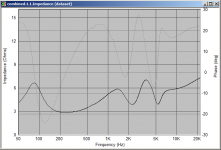
2nd pic is the impedance plot. Note that these are the simulated results but the actual results are very close to this.
Tony.
No problems so far with the amp, and to my ears (and anyone who has heard them so far) they are very natural sounding.
Attached shows the difference in the response with and without the 1.4Khz // LCR ( Blue is without in case it wasn't obvious
). 2nd pic is the impedance plot. Note that these are the simulated results but the actual results are very close to this.
Tony.
Attachments
I also vote for getting some cheap measurement gear instead of blindly buying crossover components that *might* solve it but probably not. It's not like midrange inductors are cheap so if you don't get it perfect the first guess you'll probably have spent in vain as much as a cheap microphone costs.
Then simulate a notch with some software or spend a little more money and get an analogue or digital DSP and just create an EQ notch. Much more simple and opens the doors for more fancy stuff =)
Hi OllBoll
My though is a DSP after a SOTA dAC will ruin its quality but in the professionnal world where the impedance are matched and devices slaved with standalone clock. Look at all the DSP : they have no BNC with true 75 ohms, different clocks, not asyncronous or not slaved with a Master clock : quality is most of the time not matched and depend from the weak link : it's not about just correcting fhz curve or in the better scenario phase of the driver also !
- DSP between the DAC and the pre in analog domain: a joke, not to have to say why. But MiniDSP sells one of the two DIRAC like this !
- DSP between the source and the DAC : often SPIDF, no BNC plugs, jitter source. MiniDSP sells one like this also.
- DSP before the amp : active speaker : quality of the original DAC is ruined if this last is SOTA because most of time DSP far worst than the digtal to analog of the DAC ! : MiniDSP, Hypex and others. Only serious if no DAC before but just the source : So DSP and DAC is on the same PCB with serious analog stage (remenber : one of the great concern with DAC is the analog output).
- multi DAC amp : the only way to go if DSP IMHO but nothing good nowadays yet (it will come as very pragmatic : less devices, less problem to increase quality maybe !... one problem, electronic industry have no interrest to sell less components)
I more and more surmise a systeme to be good if builded to A to Z no link by link; and DSP are in 99 % selled alone ! So in the traditional approach (link by link so with passive speaker, I stay myself with passive filter because the match with anolg stage and pre is better for the results, than all this mix of unmateched impedance, D/A and A/D, etc.
My question would be more in the direction : when too muc h passive filtering could be cause more bad result than a fastly added DSP in a classic system ! in regards to the security of the amp also.
Best of course is digital DSP before the DAC, but after the DAC works as AD/DA conversion on the chips are usually good enough. Probably not be as good as the original DAC though so digital before DAC is always better.
And about clocks, most off the shelf DSPs reclock the signal so unless you have low latency as a requirement it shouldn't be an issue.
And about clocks, most off the shelf DSPs reclock the signal so unless you have low latency as a requirement it shouldn't be an issue.
Hi Presscot,
Is your speaker adequately filled with acoustic damping material? The reason I ask is because several years ago I was asked to look into the problems of a 2 way active loudspeaker employing an 8” bass/mid-range driver together with a 1” dome tweeter in a ported enclosure.
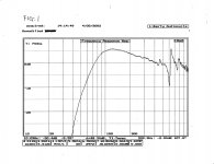
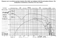
Upon inspection, I found that the enclosure had no internal acoustic damping material. Before I did anything else, I made a high-resolution near-field measurement as shown in Fig.1.
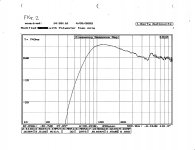
The peaks and dips in this response were dramatically reduced in magnitude (as shown in Fig2) when I applied 1.5” thick acoustic grade open cell foam to the internal walls of the enclosure. Needless to say, these peaks and dips were caused by standing waves inside the enclosure and as you can see, are right in the frequency range you refer to in your OP.
This kind of problem is not easily solved with analog filters though, especially since there are simple ways to fix it.
There are many things that can cause the problem you describe like for instance, an inadequately braced enclosure, an inadequate baffle step correction (BSC), or if you have a ported design, it could even be a port resonance. The best way to find out is to start making electrical and acoustic measurements.
Peter
Is your speaker adequately filled with acoustic damping material? The reason I ask is because several years ago I was asked to look into the problems of a 2 way active loudspeaker employing an 8” bass/mid-range driver together with a 1” dome tweeter in a ported enclosure.
Upon inspection, I found that the enclosure had no internal acoustic damping material. Before I did anything else, I made a high-resolution near-field measurement as shown in Fig.1.
The peaks and dips in this response were dramatically reduced in magnitude (as shown in Fig2) when I applied 1.5” thick acoustic grade open cell foam to the internal walls of the enclosure. Needless to say, these peaks and dips were caused by standing waves inside the enclosure and as you can see, are right in the frequency range you refer to in your OP.
This kind of problem is not easily solved with analog filters though, especially since there are simple ways to fix it.
There are many things that can cause the problem you describe like for instance, an inadequately braced enclosure, an inadequate baffle step correction (BSC), or if you have a ported design, it could even be a port resonance. The best way to find out is to start making electrical and acoustic measurements.
Peter
Attachments
Out off topic sorry :
maybe Asynchronous but the problem with interfacing a DSP with a SOTA standalone DAC stays problematic... But off course standalone project with the DAC thinked around like we can see with Bufallo 3 and rasberry projects maybe.
I'm not totaly honnest in relation to my last post. I think Source/streamer able to manage local Network (and not anoying SD card but for the travellers) with EQ/DSP phase stable is the future and will be the only way for me to swap from my 2 SB Duet ! The day when this source should be able to be also slaved from the Master clock of the SOTA DAC with uf.l wire AND of course to have good asyncronous also And able to to manage 16 to 32 bits DAC ! With uf.l I2S wires and/or BNC toimpedance boards matching. Does it exist ? Say: with good quality tofight all the embeded USB DAC (AMR, AUDIAL, AYRE e.g. ?)
For the moment i stay with my passive Boston Acoustic and the passive filter... where I hesistate to add two notc trap like (one in the tweeter and one in the mid) i did with the tweeter... It goes in the opposite direction (but Urban Myth ?) than a simple filter with low order and less components is always better !
I add I have also a Kef 104/2 ref with a complex filter which sounds very well with a good soundstage ! Well can we add two or more trap notch in domain fhz with no problem but a lake of dynamic or life ?
maybe Asynchronous but the problem with interfacing a DSP with a SOTA standalone DAC stays problematic... But off course standalone project with the DAC thinked around like we can see with Bufallo 3 and rasberry projects maybe.
I'm not totaly honnest in relation to my last post
. I think Source/streamer able to manage local Network (and not anoying SD card but for the travellers) with EQ/DSP phase stable is the future and will be the only way for me to swap from my 2 SB Duet ! The day when this source should be able to be also slaved from the Master clock of the SOTA DAC with uf.l wire AND of course to have good asyncronous also And able to to manage 16 to 32 bits DAC ! With uf.l I2S wires and/or BNC toimpedance boards matching. Does it exist ? Say: with good quality tofight all the embeded USB DAC (AMR, AUDIAL, AYRE e.g. ?)For the moment i stay with my passive Boston Acoustic and the passive filter... where I hesistate to add two notc trap like (one in the tweeter and one in the mid) i did with the tweeter... It goes in the opposite direction (but Urban Myth ?) than a simple filter with low order and less components is always better !
I add I have also a Kef 104/2 ref with a complex filter which sounds very well with a good soundstage ! Well can we add two or more trap notch in domain fhz with no problem but a lake of dynamic or life ?
Hi Presscot,
Is your speaker adequately filled with acoustic damping material? The reason I ask is because several years ago I was asked to look into the problems of a 2 way active loudspeaker employing an 8” bass/mid-range driver together with a 1” dome tweeter in a ported enclosure.
Upon inspection, I found that the enclosure had no internal acoustic damping material. Before I did anything else, I made a high-resolution near-field measurement as shown in Fig.1.
The peaks and dips in this response were dramatically reduced in magnitude (as shown in Fig2) when I applied 1.5” thick acoustic grade open cell foam to the internal walls of the enclosure. Needless to say, these peaks and dips were caused by standing waves inside the enclosure and as you can see, are right in the frequency range you refer to in your OP.
This kind of problem is not easily solved with analog filters though, especially since there are simple ways to fix it.
There are many things that can cause the problem you describe like for instance, an inadequately braced enclosure, an inadequate baffle step correction (BSC), or if you have a ported design, it could even be a port resonance. The best way to find out is to start making electrical and acoustic measurements.
Peter
Hi Peter,
Does it solve the problem of peaks without adding others properties : less clearness and details, more smothered sound (in the sens: less dynamic, less life) ?
I tried passive correction but in the front bafle (several materiels tested) without sucess in the treble for a 3 db peak...
Is the swap to 50% full in the box with near 100 % can flat enough bad box, bad load, or big peaks from the driver itself ? Materials known to be better than others at choosed frequencies ?
For shouty midrange, make sure it is not the ceiling or wall reflections. My room is notorious for shouty mids, but it vanished when I tried a 50deg vertical dispersion horn, SEOS12. later I put diffusion and absorption on the ceiling which helped the non-horn speakers.
For a quick experiment, put an absorptive blob of something above and forward of the speaker, in the path of ceiling reflection of tweeter to ears at listening spot. Like maybe a pillow on a board cantilevered from top of speaker. Also try damping the side reflections with hanging quilts or something, but damping close to the speaker is much more effective.
For a quick experiment, put an absorptive blob of something above and forward of the speaker, in the path of ceiling reflection of tweeter to ears at listening spot. Like maybe a pillow on a board cantilevered from top of speaker. Also try damping the side reflections with hanging quilts or something, but damping close to the speaker is much more effective.
Update!
Thank you for all the answers. Your all answers are very useful to me and have brought me to the solution! 
I've found a solution to my problem. I have achieved with a Baffle Step correction (BSC).
First, I thought to myself I should have built a notch filter to solve on my problem. So, I tried on this link - mh-audio.nl - Home. After calculating and testing, it worked not so bad. The spike (female vocal) has been removed ..but slightly . So, I reconsidered about my situation and thought again.
As my woofer has been used as a full-range -- the x-over point has been set up by its roll-off (4kHz for my seas h602). I went for a try on this calculator - mh-audio.nl - Home and I went back to this one again - mh-audio.nl - Home. To the second part, An amplitude parallel notch calculation, it shows how the circuit works. I put the values from my bsc calculation and notch filter calculation into it and then when the result arrived, I took the values out to be plotted the graphs on a microsoft excel to see how it shapes.
After comparing a graph, I chose "BSC". It use 1.8mh parallel with a 6.1 ohms resistor and placed them series with a driver. The result is... it works well! Those spike has been almost removed ...but there still remain some harshness on female's reaching high notes. So, I tried to add a 1 ohm resistor into it to make a resistor much higher value, and so now! the sounds right to my ear. 
Thank you very much for all your kind of help and suggestions.
Thank you for all the answers
. Your all answers are very useful to me and have brought me to the solution! I've found a solution to my problem. I have achieved with a Baffle Step correction (BSC).
First, I thought to myself I should have built a notch filter to solve on my problem. So, I tried on this link - mh-audio.nl - Home. After calculating and testing, it worked not so bad
. The spike (female vocal) has been removed ..but slightly . So, I reconsidered about my situation and thought again.As my woofer has been used as a full-range -- the x-over point has been set up by its roll-off (4kHz for my seas h602). I went for a try on this calculator - mh-audio.nl - Home and I went back to this one again - mh-audio.nl - Home. To the second part, An amplitude parallel notch calculation, it shows how the circuit works. I put the values from my bsc calculation and notch filter calculation into it and then when the result arrived, I took the values out to be plotted the graphs on a microsoft excel to see how it shapes.
After comparing a graph, I chose "BSC". It use 1.8mh parallel with a 6.1 ohms resistor and placed them series with a driver. The result is... it works well!
Those spike has been almost removed ...but there still remain some harshness on female's reaching high notes. So, I tried to add a 1 ohm resistor into it to make a resistor much higher value, and so now! the sounds right to my ear. Thank you very much for all your kind of help and suggestions.
Last edited:
Pay attention if you are using a resistor in series with the driver (woofer) for the power admissible and that of the amp. Maybe I'm missing here something, but that's not a good idea....So, I tried to add a 1 ohm resistor into it to make a resistor much higher value, and so now! the sounds right to my ear.
Thank you very much for all your kind of help and suggestions.
Do a FRD/ZMA simulation of the drivers, crossovers and baffle/speakers with any free software available and post it here in diyAudio for analysis, if you want to go in the right direction.
Pay attention if you are using a resistor in series with the driver (woofer) for the power admissible and that of the amp. Maybe I'm missing here something, but that's not a good idea.
Do a FRD/ZMA simulation of the drivers, crossovers and baffle/speakers with any free software available and post it here in diyAudio for analysis, if you want to go in the right direction.
Thanks for provided more information.
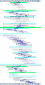
I don't know whether the resistor will effect on my woofer but I'd wiring the circuit like this (image 1). So, it would be kind if anyone just comment on this.
Note : I've added a zobel network altogether.
For the program analysis, I must confess that it's maybe hard for me to learn about a new technology
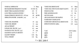
. So, the way I'm using at present is only listening test. I listen to a sound and then I compare things which I heard with this table chart. (image 2) P.S. Now I found a little bit of spike. Barbra Streisand has shouted on me
 - especially in the song named "Woman in love"
  . So, I'm looking for Barbra Streisand's range and kill it.
 Attachments
You will have to make a speaker for each individual/band and record that way...P.S. Now I found a little bit of spike. Barbra Streisand has shouted on me
What drivers do you have after all, if you don't mind me asking after 33 posts?!
Oh sorry! Forgot to tell a basic information.
Seas h602 p17rex/p.
THIS is what is needed for any meaningful discussion, my friend!Oh sorry! Forgot to tell a basic information.
Seas h602 p17rex/p.
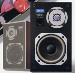
It's a Frankenstein box consisting of a Denon SC-C3 speaker with the woofer replaced by a rather impressive SEAS P17REX/P 17cm. polypropylene cone with phase plug.
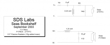
So far, crossover work is rudimentary to say the least. SDS labs publish something that might be adaptable.
Attachments
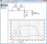
So, it would be kind if anyone just comment on this.
Your current circuit doesn't look bad (see attached simulation). Personally I would go for a 2nd order low-pass filter in order to attenuate the peak at 3.7 kHz somewhat. Perhaps Barbra Streisand then wouldn't shout anymore.

Without knowing anything about the tweeter it's difficult to say more.
Attachments
THIS is what is needed for any meaningful discussion, my friend!
It's a Frankenstein box consisting of a Denon SC-C3 speaker with the woofer replaced by a rather impressive SEAS P17REX/P 17cm. polypropylene cone with phase plug.
So far, crossover work is rudimentary to say the least. SDS labs publish something that might be adaptable.
Thank you for your hospitality and friendship.
Your current circuit doesn't look bad (see attached simulation). Personally I would go for a 2nd order low-pass filter in order to attenuate the peak at 3.7 kHz somewhat. Perhaps Barbra Streisand then wouldn't shout anymore.
Without knowing anything about the tweeter it's difficult to say more.
It's a shame that I didn't know about my tweeters too
since they were belonged to that original Denon speaker. But only known is they are 6 ohm drivers and were crossed at 4 kHz with 2nd-order Linkwitz-Riley -- using only 3.3uF in series and 0.47mH in parallel, no L-pad or other filter on it.
Last edited:
Wow! what an amazing I'm seeing at your attached file.Your current circuit doesn't look bad (see attached simulation). Personally I would go for a 2nd order low-pass filter in order to attenuate the peak at 3.7 kHz somewhat. Perhaps Barbra Streisand then wouldn't shout anymore.
Without knowing anything about the tweeter it's difficult to say more.
I looked forward to see this for a long time. Could you please suggest me about this program ?
I think if I could have this, I may sometimes do my speaker better.
Now, I've known one more thing, which I used to suspect for a long time, that at 500-2kHz is a problem of mine. This one has ensured me.- Status
- This old topic is closed. If you want to reopen this topic, contact a moderator using the "Report Post" button.
- Home
- Loudspeakers
- Multi-Way
- Notch filter for midrange ???