Revised build instructions, rev 2!
Ok I had a chance during lunch to go through and revised some more of the build instructions. A new revision is below and out at the Google Drive link.
I had previously just made my way through the build sections, starting with "1. Solder in the power jack..." This time I've gone through the initial parts up to that point.
Eveything has been gone through at this point except the "theory of operation" section at the bottom. I'll still go through them again this weekend and see if I can pick up any more things I missed. Please let me know if you spot any more part numbers being off, or any other part of the instructions that can be improved. Thanks!")
Ok I had a chance during lunch to go through and revised some more of the build instructions. A new revision is below and out at the Google Drive link.
I had previously just made my way through the build sections, starting with "1. Solder in the power jack..." This time I've gone through the initial parts up to that point.
Eveything has been gone through at this point except the "theory of operation" section at the bottom. I'll still go through them again this weekend and see if I can pick up any more things I missed. Please let me know if you spot any more part numbers being off, or any other part of the instructions that can be improved. Thanks!
Attachments
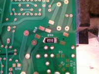
First .51 ohm R18 in place!!!
Alex
Hey you are on your way!
Good soldering work on that resistor too.That is not quite it yet on the bass boost. I've just posted a revision of the build instructions and I re-wrote that bass boost section. Take a look and let me know if it is clearer. If you are using boost you should wind up with four 3K resistors and no 1.5K resistors around those gain chips. With no bass boost you wind up with no 3K resistors and just two 1.5K resistors.
Yep, with bass boost you get a 3dB boost. Without bass boost then the frequency resposnse is just flat, as with the O2 headamp.
Last edited:
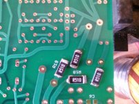
All Four...
Kool....I understand that, I want no bass boost to compare with the O2.
I might go back in and add the switch and resistors/caps and the 1.5K to see how that sounds..
Just ordered a Red Case and the 24vac 1.8 amp xfmr..
Alex
Kool....I understand that, I want no bass boost to compare with the O2.
I might go back in and add the switch and resistors/caps and the 1.5K to see how that sounds..
Just ordered a Red Case and the 24vac 1.8 amp xfmr..
Alex
Attachments
Last edited:
Great!! This is clear!
If bass boost is not used, then R24 and R25 are 1.5K, with R22, R23, C15, & C16 not used (not populated). If bass boost is used then R22 - R25 are all 3K as shown in the BOM for the "optional" boost.
Alex
Note: May want to include a Mouser PN for a DPDT?
If bass boost is not used, then R24 and R25 are 1.5K, with R22, R23, C15, & C16 not used (not populated). If bass boost is used then R22 - R25 are all 3K as shown in the BOM for the "optional" boost.
Alex
Note: May want to include a Mouser PN for a DPDT?
Alex - good idea on the switch part number! I'll add that. Yeah that is a good point about the bass boost, it can always easily be added later. There is no need at all to add boost during the initial build-up. The two feedback resistors R24 and R25 would have to come out and be replaced to add boost, but they are large(er) through-hole resistors. Getting them out should be relatively easy.
BTW, there is a design reason why R24, R25, R31, and R32 are through-hole resistors and are the longer 6mm size. Those are "low current noise" resistors that are not avalable in the small 3mm 1/8W form factor. The feedback circuit and the attenuation circuit are two places running higher currents, especially those R31 and R32 resistors. 10 times more current going through the output section than with NwAvGuy's O2 and the 10K pot. It is a tiny addition to the overall noise floor reduction, but every little bit adds up. I originally wan't going to use the low current noise resistors in the feedback spots (R24 and R25), but noticed I had board space so I made the addition.
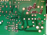
Looking good with those four resistors! Now everything gets a little smaller (1206 sized) from here.
BTW, there is a design reason why R24, R25, R31, and R32 are through-hole resistors and are the longer 6mm size. Those are "low current noise" resistors that are not avalable in the small 3mm 1/8W form factor. The feedback circuit and the attenuation circuit are two places running higher currents, especially those R31 and R32 resistors. 10 times more current going through the output section than with NwAvGuy's O2 and the 10K pot. It is a tiny addition to the overall noise floor reduction, but every little bit adds up. I originally wan't going to use the low current noise resistors in the feedback spots (R24 and R25), but noticed I had board space so I made the addition.
Looking good with those four resistors! Now everything gets a little smaller (1206 sized) from here.
Last edited:
Ok time for a break...
Those small 1206 parts are indeed a challenge.
Advice is GO SLOW...and recheck joints...I measure the values from a point away from the part if a resistor....just to be sure.
The cap value I guess we need to trust Mouser, I don't have a cap bridge or meter...
This is not first time DIY for sure....
LOL
Alex
Ok finally got to solder some of those SMD 1206 parts!!!
They are an eye test for sure.
Its even a pain to get them out of their packaging!!!
Advice" GO SLOW and recheck your joints....have to use my most powerful WalMart 3x readers!!
LOL
Time for a break or a beer!
Sorry for the crappy focus, its my shakey hands an phone!
Alex
They are an eye test for sure.
Its even a pain to get them out of their packaging!!!
Advice" GO SLOW and recheck your joints....have to use my most powerful WalMart 3x readers!!
LOL
Time for a break or a beer!
Sorry for the crappy focus, its my shakey hands an phone!
Alex
Attachments
Last edited:
In Step 1 of the Build Instructions indicate R13, R16, R19, R20, R21, R71, R78, R82 , C5 and C9.
I think C9 was meant to be C6, the snubber cap?
Alex
Yep, another good find! Fixed. I just re-posted the build instructions at the Google Drive link. I know how it happened. The text on the parts under the board is mirrored on the layout, so C6 looks like C9.
I was onto that though and used the actual layout editor rather than the PDF image for most of the build instruction editing, so I could call up the part name directly and make sure I wasn't reading it backwards. But I definitely missed that one.Hey good work on your 1206 parts. If you can find one of those cheap "helping hand: magnifying glasses on a stand like this
Amazon.com: SE MZ101 Dual Helping Hands with Magnifier: Home Improvement
it can help a great deal, although keeping them from tipping over is a constant pain. Yeah the best way to get the 1206's out of the strip is hold the strip over the board, peel back as much of the clear strip on the top as needed, then just flip the strip and "dump" the part(s) out on the board. Then it is all tweezer time from there.
Last edited:
One of the most difficult part to decide on for me is the PRE AMP choices...there is a lot of flexibility here for sure.
I don't really think I would use the preamp function at all.
I had a Schitt Lyr and never used the pre outs on it ever.
The main reason for the ODA is to have a world class amp that exceeds the O2 in measurements, has that 1/4 phone jack, a very low output impedance, etc....
So a purists headphone amp. Hence the no bass boost etc...
So I think I will most likely not wire the pre amp up at this time. But I might change my mind in a day or two!!!
LOL
Alex
Can the all the 0 ohm resistors be replaced with 22 ga wire?
I didn't order any of the actual 0 ohm smd parts??
Alex
That definitely works. For the super small R1 and R2 that might even be the preferred way. For R1 and R2 it could even be tiny 28 gauge wire wrap wire.
One of the most difficult part to decide on for me is the PRE AMP choices...there is a lot of flexibility here for sure.
I don't really think I would use the preamp function at all.
You can certainly just leave the pre-amp out unused. If the pre-drilled panel is being used though probably a good idea to at least solder in the pre-amp RCA jacks to cover the holes. Plus then you can always add it later.
That is another build instruction thing I forgot to mention. The pre-amp section is not filled in yet, and I have not done the pre-amp photo build either. The reason is Mouser.
I want to try using the NJM MUSES8820E chip in there, which I bought a couple of weeks ago. But... it arrived from Mouser without any anti-static packing! Just in a plain clear plastic bag, with clear (not anti stat) bubble wrap around it. I reported the packing problem and they are still working on it. Mouser says they are waiting for "moisture sensitivity level" packing info from JRC now and don't want to ship a replacment until they get it. First packing problem of any kind I've run into with Mouser. Makes me wonder if their entire stock will have to be trashed and re-ordered if it wasn't being handled in an anti-stat manner. I imagine that whole pick and pack system is robotic and it is all how each part is programmed to be packed. I'll fill in that pre-amp section in the build instructions this weekend and re-post them. A LME49720 could be used there instead, or for pass-through wiring no chip is needed at all.
Hey something unrelated but interesting. I ran into an article from 2011 last night that I've read through before, but noticed something new this time. It is Doug Self's small signal op amp EE Times article here:
http://www.eetimes.com/document.asp?doc_id=1278805&page_number=2
That writeup on slew rate (scroll down) is worth a read after all that discussion over on Head-Fi about slew rate. I know that NwAvGuy / RocketScientist liked Self's work. The article here echoes what NwAvGuy wrote, that the 3V/uS slew from the NJM4556A is more than adequte for audio. But the part I had missed before is about the LM741's. Note their slew rate in the table is just 0.5V/uS, which would mean bad for audio. Yet he notes they were used for years and nobody complained. And the interesting reason is only the high(er) frequency end of audio is what starts bumping into the slew rate, and high frequencies are usually not high amplitude (loud) in music or voice. He is right. It is the low bass notes that wind up getting the large voltage swings for more power. Who would want to listen to a 7Vrms 15KHz note via headphones? Lol - that would be like listening to a smoke alarm going off overhead. Interesting stuff.
Last edited:
Cool, I have both the front and rear RCA plugs...so I will install them front and back but wait on the actual parts and wiring etc....need to think on how I would ever use them.
Its funny in my days past I never used or even heard of zero ohm jumpers or seen an actual 0 ohm resistor...we just bridged solder or a small piece of buss wire, or wire wrap 28 or 30 ga etc depending on the current draw etc...yes those tiny little 0 ohm resistors do look better though...LOL.
Doing yard work today will start soldering again tonight...
I will take a pix of my vise, its a 20 plus pound drill press vice that stays put and works well for me.
I have been lighly "tinning' the 1206 smd pads and then tacking one side then the other let cool and redo both with a little more solder. Then check with a meter for values from holes near the component.
Lunch time..and thanks for the slew rate info...wow the venerable 741 op amp...and oldie but a "goodie???" LOL.
Later
Alex
FYI,
I have started a discussion on audiocircle.com in the headphone "circle" area of their forum about the ODA.
I posted a link to the DIY site for this thread as well.
Lots of interest...mainly in what it is vs the O2, but they have some concerns with the SMD small parts...so a purchase option for the board or total build is viable to some.
One question they are asking is why SMD parts, why not the usual ones...??
I can guess at the answer, but will allow you to expound!!
Alex
I have been lighly "tinning' the 1206 smd pads and then tacking one side then the other let cool and redo both with a little more solder. Then check with a meter for values from holes near the component.
Tinning them can't hurt. That gets the 1 second or so worth of rosin cleaning and solder adhesion to the metal part out of the way. When you go to heat up the pad and stick the part end in, everything should be immediate then.
FYI,
I have started a discussion on audiocircle.com in the headphone "circle" area of their forum about the ODA.
I posted a link to the DIY site for this thread as well.
Lots of interest...mainly in what it is vs the O2, but they have some concerns with the SMD small parts...so a purchase option for the board or total build is viable to some.
One question they are asking is why SMD parts, why not the usual ones...??
I can guess at the answer, but will allow you to expound!!
Alex
Good question! The SMD stuff was purely for size reasons, to be able to fit it all in the box. My goal in designing it was to use as much through-hole stuff as possible, only going to SMD when I had to for space. That is why the 274R input series resistors by the RCA jack are through-hole, but the same thing by the 3.5mm jack are SMD. Also take a look at the layout around the relay. I only went to SMD parts when I ran out of board top space, like the 2 SMD resistors in that section sitting underneath some unused space under the 1/4" jack.
If Box Enclosures made an even wider box I would have probably used it. I have to use the 10cm x 20cm fab option at Seeed Studio to fit the 8cm x 16cm board, so I'm essentially having to leave 4cm worth of fab ability (width), which wouldn't cost a nickle more to use, on the table each time.
One of the forum members has written me before about being able to custom print a larger box with a 3D printer that would use that entire 10cm x 20cm space! The one hiccup with that though is the plastic. This one needs to be metal for the heat dissipation from those heatsinked voltage regulators.
Also, regarding bass boost, one of the "things to do someday" projects I have in mind is a parametric bass boost card (state variable filter) that would slide into the top slot of the box and work with any version of the ODA board. That would essentially be a "bass boost on steroids".
It would allow not only the level of boost to be controlled from a front panel pot, but also the frequency break point of the boost. I wouldn't do mid or treble, just bass since I think a fair number of headphones fall down in bass reproduction. Just take a look at the frequency response plots that Tyll did out on headphone.com for all the various headphones. I know the same thing can be done digitally with the media player eq, but it is just kind of nice having a couple of analog pots to turn.
Last edited:
First mechanical fit issue, D16 1 amp 400v 1N4004GP E3/E4 diode doesn't fit in the hole for D16. D15 is ok, its a smaller dia set of leads on that diode (1N5260B-TR).
Same for D3, D4, D5 and D6.
Will try to open up with a small drill or "sand" down the diode leads carefully etc.
Alex
Same for D3, D4, D5 and D6.
Will try to open up with a small drill or "sand" down the diode leads carefully etc.
Alex
In the build instructions page 10, where it says "So these are IC11, R70, R79, R83, R84, R85, C49, C50, C61"...
C61 is part of the Zorbel network...so this probably should not be in this list?
Also not on the schematic, near the Zorbel network, there is a note that indicates the parts to be left out R78, R79, C74 and C75, are these correct??
(the build instructions have R86, R87, C60 and C61).
Alex
C61 is part of the Zorbel network...so this probably should not be in this list?
Also not on the schematic, near the Zorbel network, there is a note that indicates the parts to be left out R78, R79, C74 and C75, are these correct??
(the build instructions have R86, R87, C60 and C61).
Alex
- Home
- Amplifiers
- Headphone Systems
- A version of an O2 Desktop Amp (ODA)