The lower 2 graphs show a ~5 Ohm impedance at 0.5 MHz. The impedance equation 5 Ohm = 2 x Pi x 0.5E6 xL calculates L~ 2 microHenry.Hello. I did not see a value for their inductance. The site showed graphs of their impedance as a function of frequency starting at ~0.5 MHz. Maybe a DIYer has an answer.
Best regards
Well done to the patent office - what a bunch of amateurs... No way this would stand up in court with so much published prior art!
The "new twist" was apparently the limitation in the claims that the "primary" amplifier is an IC, not discrete.
And thats somehow is Patentable??? "you" (not you personally) have to be joking right?
Back in the days of the arguments over Quad Current dumping IIRC a guy from India demonstrated various arguments in letters to Wirelessworld using a Philips IC.... so "prior art" although its a real stretch to call it "Art" - also I've seen schematics over the years with power IC's and current dumping stages (but they where hardly worthwhile noting, so I've not bothered to saved them)...
Back in the days of the arguments over Quad Current dumping IIRC a guy from India demonstrated various arguments in letters to Wirelessworld using a Philips IC.... so "prior art" although its a real stretch to call it "Art" - also I've seen schematics over the years with power IC's and current dumping stages (but they where hardly worthwhile noting, so I've not bothered to saved them)...
Last edited:
I hope that you'll excuse my ignorance. Is/was Quad a Japanese audio supplier.The references Linn cited in its patent are Japanese patents.The Quad circuits have similar inductor values. Their patent claims centred on the bridge inductor and glossed over the output device "slow down" inductors, which they did not consider novel enough to be in the claims
The Quad circuits have similar inductor values. Their patent claims centred on the bridge inductor and glossed over the output device "slow down" inductors, which they did not consider novel enough to be in the claims
And quite rightly so.... it’s a known circuit technique - even used in ClassD designs (small inductor values on the Source legs of the output devices) to limit shoot though currents.
Linn just demonstrates how amateurish they are by patenting a common circuit technique with some naive belief it’s something unique.
I guess if anyone was really concerned about it – a more eloquent solution is to add small Base resistors….
If you were reading Wireless World in the mid 70's you could not escape the articles and heated debate by letter about the Quad 405 "Current Dumping" circuit and patent.I hope that you'll excuse my ignorance. Is/was Quad a Japanese audio supplier.The references Linn cited in its patent are Japanese patents.
Quad were as British as you could be in those days.
The Japanese patents are there because their companies were patent mills, producing mountains of frequently trivial variations. I suspect the Quad patent is "conveniently" overlooked
Thank you for the clarification.If you were reading Wireless World in the mid 70's you could not escape the articles and heated debate by letter about the Quad 405 "Current Dumping" circuit and patent.
Quad were as British as you could be in those days.
The Japanese patents are there because their companies were patent mills, producing mountains of frequently trivial variations. I suspect the Quad patent is "conveniently" overlooked
Long ago, before simulators became common, I built a mini "Current Dumper" to see how it actually worked. This had a TL071 as the "quality amplifier" and a couple of E-line transistors with series inductors to reduce the conduction overlapThe "new twist" was apparently the limitation in the claims that the "primary" amplifier is an IC, not discrete.
And quite rightly so.... it’s a known circuit technique - even used in ClassD designs (small inductor values on the Source legs of the output devices) to limit shoot though currents.
Linn just demonstrates how amateurish they are by patenting a common circuit technique with some naive belief its something unique.
I guess if anyone was really concerned about it – a more eloquent solution is to add small Base resistors….
Ops - I meant to say "small inductors to limit peek shoot-through currents on the DRAINS of the switching devices" not the Source leg.
http://www.qobuz.com/info/IMG/pdf/linn-chakra-white-paper.pdf
http://www.qobuz.com/info/MAGAZINE-ACTUALITES/HI-FI-BANCS-D-ESSAI/Banc-d-essai-Linn-Majik-DSM134187
In fact it is the same as here :
http://www.diyaudio.com/forums/chip-amps/206591-tda7294-power-transistors-amp-tda7293-come-also.html
http://www.qobuz.com/info/MAGAZINE-ACTUALITES/HI-FI-BANCS-D-ESSAI/Banc-d-essai-Linn-Majik-DSM134187
In fact it is the same as here :
http://www.diyaudio.com/forums/chip-amps/206591-tda7294-power-transistors-amp-tda7293-come-also.html
Last edited:
This is hard to believe for me - go to the schematic by post #42 underThis is exactly what is done in every Quad design from the 405 and the 306. There are inductors around the dumper devices to smooth the switching discontinuities. These inductors should not be confused with the main inductor in the output bridge circuit.
http://www.diyaudio.com/forums/soli...c-conversion-amplification-hca-circuit-5.html and to the attached image (L800 until L803).
At the chakra amp the inductors are in series to the emitters of the power output stage. Additional - the quad 405 uses for the low wattage area a single ended power stage. This isn't the case at the TDA7293 front-end.
Attachments
This is hard to believe for me - go to the schematic by post #42 under
http://www.diyaudio.com/forums/soli...c-conversion-amplification-hca-circuit-5.html and to the attached image (L800 until L803).
At the chakra amp the inductors are in series to the emitters of the power output stage. Additional - the quad 405 uses for the low wattage area a single ended power stage. This isn't the case at the TDA7293 front-end.
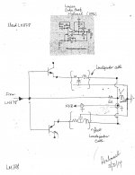
Hello tiefbassuebertr and DIYers. The attached picture shows the following:
- The top part is an example of an old schematic under current discussion less inductors attached to the emitter legs per the valid Linn patent.
- The lower hand-drawn portion proposes a simulation, and a non-commercial schematic which utilizes two loudspeaker cables as part of the bjts' emitter circuits.
- The article "Speaker Cables: Science or Snake oil" by Nelson Pass [www.firstwatt.com], shows a simple model of a loudspeaker cable in Fig.1.
- Each foot of a 2-conductor loudspeaker cable is represented by a network of a resistor, a capacitor and an inductor as I show in the attached bottom portion of the picture.
- One may wish to study a loudspeaker cable at several lengths, and/or many commercially available cables.
- A legitimate objective of this proposed study is an attempt to improve upon the Linn patent. Noting that any patent is merely a stepping stone to create future inventions if desired. There's absolutely nothing wrong or illegal to pursue such studies.
- May wish to demonstrate that a 10 foot 18 gauge zip cord [for example] per output bjt gives an "amplifier system" having a performance that is superior to the Linn amp. Wishful/optimistic thinking by me as the proposed "amplifier system" [aka LM378 amp plus 2n feet of loudpeaker cables] may oscillate and/or perform way worse than the parent by National, or by the Linn am; both used as prior art or references in the study.
- Loop NFB starts at the loudspeaker terminals. Reminds me of Kenwood's Sigma Drive.
Attachments
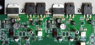
Here is a picture of the Klimax Chakra 500 TWIN prototype.
My suggestions for the marked areas are:
A. Bipolas with "Chakra" inductors (obvious)
B. OpAmp for ??? (most likely a DC-servo ? in the feedback path), you will find this in every Linn amp with Chakra circuit.
C. Sense resistors. Most likely sensing the V+ and V- current through the TDA and the bipolars. As the manual of the klimax tells us, the amp will monitor the current and will turn-off the amp in case of ultra high current. You will find this also in all Linn amps.
D. Boucherot network
E. A pair of diodes to minimize inductive backloads.
F. Most likely a quad OP-AMP. But what for ? The Klimax senses the input and turns-on when the audio input is >100µV. This quad could do this and at the same time acts as an input buffer (?).
G. This is R1 in the patent circuit.
Any other suggestions ??
Ideas and questions welcome.
Hello,
If C are sense resistors, sensing V+ and V- current, like this :
http://www.diyaudio.com/forums/chip-amps/255719-gainclone-lm3886-tda7293-2sc2500-2sa1943-push.html
so the schematic is not like the patent...
I simulated the patent schematic and there is 1% distortion...
Last edited:
I found this topic while searching for C2200 service manual. Just today I decided to purchase used C2200 so I'm looking for manual just in case... Going through this discussion I guess it may be true that Linn's patent is questionable and price is too high for delivered amount of hardware and R&D as many of you suggest. However I've been through quite some respectable amplifiers during last months, most of them of similar rated power / price used, all solid state, class-A, A/B and latest D, and C2200 is the most pleasant surprise.
I expected relatively boring and underpowered performance but this little thing just keeps my complete attention on any music I care for, and also brings lots of new life on some other music I neglected or being irritated from so far. I can't make an A-B comparison now, but simply from my remembered impressions, of all these amps I had in my room recently, only one, several times more expensive and eight times heavier new 2x200 W A/B class amp may be overall better for my use than C2200. And if it really is so, it is not by much. On the other hand Linn C2200 is a clear winner of all the rest, except one too-hot-to-touch 50 kg class-A wonder which to me (and to couple of my friends) sounds quite similar as C2200. Therefore, thank you Linn")
The only annoyance is automatic switching off after having no signal on input for 20 minutes. Not that it bothers me in use, neither I noticed any audible changes so far, but would that be better for amplifier's longevity if it is constantly on?
I expected relatively boring and underpowered performance but this little thing just keeps my complete attention on any music I care for, and also brings lots of new life on some other music I neglected or being irritated from so far. I can't make an A-B comparison now, but simply from my remembered impressions, of all these amps I had in my room recently, only one, several times more expensive and eight times heavier new 2x200 W A/B class amp may be overall better for my use than C2200. And if it really is so, it is not by much. On the other hand Linn C2200 is a clear winner of all the rest, except one too-hot-to-touch 50 kg class-A wonder which to me (and to couple of my friends) sounds quite similar as C2200. Therefore, thank you Linn
The only annoyance is automatic switching off after having no signal on input for 20 minutes. Not that it bothers me in use, neither I noticed any audible changes so far, but would that be better for amplifier's longevity if it is constantly on?
Last edited:
- Status
- This old topic is closed. If you want to reopen this topic, contact a moderator using the "Report Post" button.
- Home
- Amplifiers
- Chip Amps
- Linn Chakra power amps revealed ...