Take a look at the transformer current modeled in PSU designer. You'll see higher RMS current than your DC draw. Because of the nature of a capacitive load and the high current charging spikes you'll get quite a bit more heating than into a resistive load. Especially into the huge capacitances we use in class A amps.
Andrew's explanation is the reason behind the rule of thumb to use a transformer with a VA rating at least twice to three times your expected load. I'm a simple guy, so I take rules of thumb and pad it a bit. I've got 400 VA per channel in my AJ and 500 VA per channel in my F5T.
Andrew's explanation is the reason behind the rule of thumb to use a transformer with a VA rating at least twice to three times your expected load. I'm a simple guy, so I take rules of thumb and pad it a bit. I've got 400 VA per channel in my AJ and 500 VA per channel in my F5T.
That tells us you are using 500VA for an amplifier...... I've been using two 500VA in a dual mono ...........
There is data missing.
The next best alternative I can offer is:
For ClassA use a transformer that is 6 to 10 times the maximum power output.
i.e. turning that back to front, 500VA is suitable for 50W to 83W of ClassA amplifier.
For ClassAB use a transformer from 1 to 2 times the maximum power output.
Last edited:
.....There is data missing...........i.e. turning that back to front, 500VA is suitable for 50W to 83W of ClassA amplifier.....
I hope this isn't going off topic, but I've approached this project with the intention of "optimizing" the quality/clarity/performance of the BA-3 design as the primary focus, and the speakers secondary. I can/will/enjoy building whatever speakers I need to hear what the amp is capable of producing if what I have now are not good matches.
It sounds like you are suggesting my approach is backwards.

500VA on it's own tells me next to nothing. It just confirms 500VA.
The previous poster told us
The previous poster told us
and then he asked his questionI have a 800VA 2x24V transformer. At the moment I plan a simple CRC filtering............ I expect about 200W dissipation capacity per channel................. I will use the big +/-32V PSU (same for the output stage)............. With those heatsinks they should be biased at 3A max per channel.
Is the transformer VA rating enough?
Last edited:
What I was keying on was both of us have a total of 24 output devices. I chose that initially for the heat management experiments, but am now more focused on the amp function and actual sound. (Kinda like - now that I have this thing, what do I do with it )
It appears that the art/science of finding the bias sweet spot is at the heart of optimization. I think what I'm learning is all the calculations and adjustments are dependent on and useless without a target - such as the requirements of the Maggies giuliodido mentions.
Is that what you are saying?
When I read the various NP articles I get the impression each iteration is focused on the uniqueness of the new circuit. That leads me to the possibly mistaken idea that the/an amp can be optimized almost independently of the power requirements of the speakers used. (Of course that's within the general published power range - ex. ACA vs. F5T)
)It appears that the art/science of finding the bias sweet spot is at the heart of optimization. I think what I'm learning is all the calculations and adjustments are dependent on and useless without a target - such as the requirements of the Maggies giuliodido mentions.
Is that what you are saying?
When I read the various NP articles I get the impression each iteration is focused on the uniqueness of the new circuit. That leads me to the possibly mistaken idea that the/an amp can be optimized almost independently of the power requirements of the speakers used. (Of course that's within the general published power range - ex. ACA vs. F5T)
Last edited:
bcmbob, I think it depends on the secondary voltage and the bias you set, and not on the number of devices used.
Andrew, thank you for the explanation. I tried to search for some more detailed information on the net, but it seems I can't find anything good. Do you have any other useful source I can examine?
Avel Lindberg offers its engineering services to help with capacitor input filter transformer rating, Antek has little tech data.
I found Power Transformer Facts Bulletin No.1 - Application Notes on Rectifier Transformers which gives a bit of insight, including a couple of old references.
http://www.plitron.com/news/technical-notes/
Last edited:

Thanks Andrew and thanks Bob for further explanations and links.
So basically I have two options:
- to decrease the bias to ~2A per channel in order to have the transformer working at the ~50% of its rating;
- to buy another transformer and keep the bias max 3A per channel; from there I can parallel them or decide to make monoblocks.
I would go for the second option, even if not cheap: I think of it as a long term project.
What about the other questions regarding JFETs matching and psu for the front end?
Thank you again
What about the other questions regarding JFETs matching and psu for the front end?
Buy matched Jfets from Spencer, (fetaudio.com) P3 is not there to fix a mismatch - it's a harmonic distortion altering tool.
The Mosfets in the front-end do not need to be matched, as the bias pots will help set everything correctly, but that mechanism is predicated on the Jfets having similar Idss.
Jim, please clarify. I'm rebuilding my BA-3 and went back to the simple FE/PS adjustments yesterday. I could not get 1V readings and zero on R13 without using P3. So are you saying once everything is brought in line - further adjustments can then be used as the harmonics tool?
".....Jfets having similar Idss" I found a few items that helped me understand some of the under the hood stuff as well as the terminology. The NP article is most likely well known by the veterans, but all three were useful for this "late to the party" guy without an EE background. They may be of benefit to others.
NP Matching/Testing Article
N-Channel Mosfet
The Mosfet
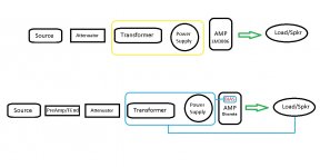
Lastly, I was stuck on Andrew's comment that stating the VA of a transformer was useless information. I drew out a super simplified diagram that might explain what caught me. Coming from my initial experience in the LM3886 world, the term "optimize" loosely refers to selecting a transformer/PS (yellow box) that allows the chip to operate at the manufacturer's maximum specs. Output is determined by the attenuation - and the speakers simply respond to those adjustments.
The discrete approach is much more deliberate and requires additional info/relationships/target (the blue stuff) for correct transformer selection. The specs of the speakers here have a higher active significance than in the "chip" example.
Am I getting any closer Andrew??

Attachments
No, Bob. As long as the jfets have similar Idss the bias pots will adjust out the small differences. If you're adjusting P# for offset you're fighting an extra battle. Stick with balancing the bias pots to get the right bias current and offset.
In the chip amp and AB amp for home use world, all you really need to do is provide a transformer that the voltage won't sag under load to reduce power available (although musical instrument amp manufacturers have been known to do that intentionally as a form of protection).
In class A, the transformer is operated at steady higher power than AB, so you need to understand what the VA rating means and how to derate the transformer for operating conditions. Most are rated at 25°C ambient into a resistive load. Put it in an enclosure at 45°C and you need to derate it. Operate into a capacitive input filter, derate again. So VA rating is not so much useless as incomplete information. You need to know more than just VA rating unless you want to use a rule of thumb and just use 3+ times the expected load.
..... Stick with balancing the bias pots to get the right bias current and offset.
OK, I'll take another shot. I didn't install multi-turn trimmers initially so that may be causing the difficulty. I have some now and should probably put them in. Is P3 simply set with turn count during this adjustment?
So VA rating is not so much useless as incomplete information. You need to know more than just VA rating unless you want to use a rule of thumb and just use 3+ times the expected load.
Fine, I understand the rule of thumb - but I'm not fully understanding "the expected load" (assuming I wanted to do the calculations). Is that simply the nominal resistance of the speaker, or is it more complex?
The VA and the power demand is needed to give a useful answer.
In your ClassA amplifier the power demand is directly proportional to the output bias current.
Tells us the bias current and we can tell you the minimum AC current rating of the transformer.
Or
Tell us the VA and the Vac and we can tell you the maximum bias current that the transformer can feed.
In your ClassA amplifier the power demand is directly proportional to the output bias current.
Tells us the bias current and we can tell you the minimum AC current rating of the transformer.
Or
Tell us the VA and the Vac and we can tell you the maximum bias current that the transformer can feed.
Bob - put the P3 to the center of it's range. Leave it there.
All the adjustments to set bias and null for zero offset can be made with P1 and P2. Sometimes it feels like a losing battle, but it will work. (Unless you run out of adjustment, but them you merely add some parallel resistance.)
Once you have everything up and set, you can then adjust P3 to taste - although in my experiments, Centered sounds really good. I have a distortion analyzer and have set for minimum THD, it's very live and detailed, but has much less soul.
OK, I'll take another shot. I didn't install multi-turn trimmers initially so that may be causing the difficulty. ...
... but I'm not fully understanding "the expected load" (assuming I wanted to do the calculations). Is that simply the nominal resistance of the speaker, or is it more complex?
Single turn pots are a major source of frustration. After building my A75s with them I swore never to use them again. Multi turn pots are well worth the extra cost.
Expected load for rule of thumb is total bias x rail to rail voltage. Say you want to bias at 3A and have 25V rails. Expected load per channel is 150W.
Look at Design Notes and Efficiencies | Plitron. It suggests that transformer current into a full wave bridge/capacitive input filter will be 1.8 times output current. So, 5.4A for 3A bias. Now multiply this by the AC voltage of the secondary to get the expected load VA. Say you have 20 VAC secondaries, so it's 108 VA PER SECONDARY. So that gives an actual transformer load of 216 VA to produce 150W into the load. Pretty darned close to Andrew's derating factor into a capacitive input filter mentioned earlier.
Now that is running at the MAXIMUM rating. The transformer will run at it's rated max temperature, heating up the amp internals. Now look at the temperature rise chart, and see the effect of using a larger transformer. Even slightly over rating the transformer makes a large reduction in temperature.
Hope that helps.
Bob, you're supplying great stuff. I'll read the links in a few minutes.
I was writing this while you posted and you have answered much with your reply. I'll post it anyway just for reference.
******
Andrew, I got a bit of insight on your reply by watching this last night.
In an attempt to clarify (and stop hogging the thread) - what I'm asking in this conversation :
All the information is useful, interesting and just plain fun. But I'm seeing two different approaches that may be circular.
1. Making adjustments to dial in on the best/highest bias the equipment I have is capable of sustaining.
2. Make adjustments that are keyed on the best match for a given set of speakers - i.e resistance and efficiency.
Those may well be a chicken or egg thing.
Another way of saying this - My Sunflower speakers are low efficiency. I have a set of MTMs that are higher and produce a stronger sound on the same amp. I perceive that adjusting some factors - such as bias - on the BA-3 can increase the output of the amp to bring the SPL of the SFs closer to the MTMs. If I do that, is it required or suggested that I also get a higher VA rated transformer to support the new bias? I have two 500VA in dual mono now. Is it reasonable to assume those have the capacity (headroom) to support higher BA-3 output? I'm not trying to blast a concert hall, but want all the components to be operating in a safe state at higher power.
I'm aware that adjusting the resistors on the output boards also influences the power of the amp, but I'm trying to get a better understanding of the sections in sequence - front end > bias boards > output boards.
Thanks Jim, I'll be installing the multi-turns later today.
You can do anything you want, just be prepared for the consequences. So, strongly suggested
To make your Sunflowers sound as loud as your MTMs, turn the volume control clockwise. If you are saying that your BA-3 is running out of power that's something else.
Assuming the push pull output, bias has nothing to do with absolute maxiumum power, just class A power. In a push pull output stage the maximum output is limited by the current capability of the stage and its ability to swing voltage. If you want more power, increase the rails.
If the single ended output option, then bias affects maximum power IF the voltage swing is there. Are the Sunflowers nominally 4 ohm speakers? (I can't remember)
To answer your question, what is your proposed bias? Remind us your transformer secondary voltage.
- Home
- Amplifiers
- Pass Labs
- Burning Amp BA-3