3.4 V @ 12 turns.
I think I should disassemble and go back to just the PS bias board combo only - as the PSU is getting too hot. I'll see how low that voltage can go and insure full action on the trimmer. I'm going to have a true "Burning Amp" if I continue in this configuration.
OK?
I think I should disassemble and go back to just the PS bias board combo only - as the PSU is getting too hot. I'll see how low that voltage can go and insure full action on the trimmer. I'm going to have a true "Burning Amp" if I continue in this configuration.
OK?
Last edited:
one DVM across one Rs - observe for desired voltage (Iq per device x R)
second DVM from output to gnd , observe/set output offset
set Iq to 70% of desired value - close lid and let it heat
open lid , increase to 90% of Iq , close lid , wait
open lid , set to Iq , close lid
wait
open lid , check ; compare U on all source resistors ; that final step needs to be in temp. equilibrium conditions
of course , observe ( and re-set if needed ) output offset all the time
it helps if you route probe wires out of case , so you can have DVM connected all the time
inputs grounded , no dummy (or any other ) load on output
Last edited:
This is the liquid cooled build and still in open frame. It will be subject to room temp fluctuations from the furnace cycles, but the process you describe is clear and puts me miles ahead of where I was. The final will include a circuit that dials in a desired running temperature and I'll readjust again at that time.
Have to do some wire re-runs, but should be able to report back later this afternoon.
Thanks
Have to do some wire re-runs, but should be able to report back later this afternoon.
Thanks
Attachments
with that cooling , you can squeeze 4V across source resistor
Will be fun to experiment, but the basic understanding gained from ya'l in the past two days was essential before that begins. It ran just a few degrees above ambient for weeks (even with those bad settings) before I took it apart to "Fix" it.


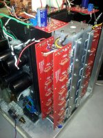
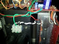
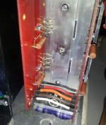
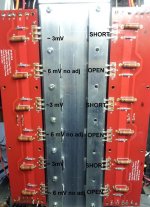
Still got gremlins. As soon as the output boards are connected the bias trimmer becomes inactive. The first picture shows power coming through the OBs. The second is feeding the bias boards directly. Both produce an unmovable 0.574 mV accross the resistors..
FIY - yesterday's high voltage readings on the resistors were due to a bad connection on the "S" link.
I did complete the full setup as described by ZM but could not make adjustments. I cycled back (4th time) and confirmed trimmer activity with PS and bias boards only. PS + bias bds + output boards is thermally stable but still no adjustments possible.
Configured one channel for sound and found good music and no hum or distortion. There is no continuity on any fet pin on that side, but a few developed on the other - probably over tightened and will repair.
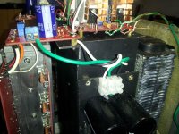
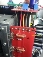
Third pic is just the star ground used for both measurements and the music test.
Is anyone aware of an independent test for some kind of loop or back-feed on the output boards?
FIY - yesterday's high voltage readings on the resistors were due to a bad connection on the "S" link.
I did complete the full setup as described by ZM but could not make adjustments. I cycled back (4th time) and confirmed trimmer activity with PS and bias boards only. PS + bias bds + output boards is thermally stable but still no adjustments possible.
Configured one channel for sound and found good music and no hum or distortion. There is no continuity on any fet pin on that side, but a few developed on the other - probably over tightened and will repair.
Third pic is just the star ground used for both measurements and the music test.
Is anyone aware of an independent test for some kind of loop or back-feed on the output boards?
Attachments
how many output pairs you have ?
desolder all gate resistor on output mosfets , except first pair (N+P) ; that way all will be Dodo , except first pair
test ; if good , solder gate resistors for next group
test .
when you solder gate resistors of critical ones , everything will go south , again and you found them
if problems persist even with just first pair - try just second pair
if problem stays , it's in your biasing stage , not mosfets
though - replace zener diodes (D101, D102) - there is always possibility that you either burn them or zapp them ....... if one is leaking , all problems can be there
It's not that bad. I still have some Heatsink USA product with holes at the right locations from the initial build. Also, it would be next to impossible to reach the inside resistor leads with my fancy stacked output boards. That water box has 1/4" walls that provide good heat absorption but a flat layout with just two OBs at a time will be more convenient.
I don't mind doing the re-work cause I always learn something new. My only regret is that I didn't buy stock in a company that makes solder wick - I'd be a wealthy man today.
I don't mind doing the re-work cause I always learn something new. My only regret is that I didn't buy stock in a company that makes solder wick - I'd be a wealthy man today.
This build was targeted at heat management so I selected the hotter SE set - there are no N/P pairs. Since most tips refer to the complimentary (and reportedly better sound) I ordered a set of those boards. Plus - I tried one SE OB at a time and they all suffered the no adjustment problem. A new partial bias board BOM (everything except resistors), and a dozen unmatched low cost fets for the SE are on the way.
I'll probably wait for the guide from 6L6 before proceeding with the comp sets. I've contacted Buzz and he can supply matched pieces when needed.
Will pick back up on this version when new parts are delivered later in the week.
I'll probably wait for the guide from 6L6 before proceeding with the comp sets. I've contacted Buzz and he can supply matched pieces when needed.
Will pick back up on this version when new parts are delivered later in the week.
Last edited:
If anybody still wants to play ???
Being both suborn and curious, I put the amp back together one more time before completely dismantling.. Found some interesting things:
1st channel plays music and three of the mosfets do adjust between 0.203 and 0.325 mV. I can hear the change in volume thru the speakers. The other three are stuck at 0.596 mV.
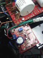
The second channel produced continuity before I could apply power again - but it is the same pattern as the first channel. My first thought was to replace the shorting three, but after taking a better look at the traces on these SE boards, see the alternating bus arrangement of the fets. The D+ and D- feeds follow that same alternating pattern and each D trace has it's own diode.
Could that indicate some of the diodes in the OBs are defective? Could be just a coincidence but looks suspicious.
Next step is swapping bias boards. New stuff coming but this has still got me pondering. Hate to give up without at least learning something.
and later that day.....
I installed one of the remaining populated output boards. Same results - no continuity to heatsink on any mosfet pin with physical mounting only. When all the signal and power wires were connected the same locations showed shorts. I pulled all the wires between the bias board and then added them back one at a time. Everything was clear till the last one, V-. Same three locations short. There are no solder bridges or other visible glitches on the V- traces on either board.
Can anybody make sense out of that one?
Being both suborn and curious, I put the amp back together one more time before completely dismantling.. Found some interesting things:
1st channel plays music and three of the mosfets do adjust between 0.203 and 0.325 mV. I can hear the change in volume thru the speakers. The other three are stuck at 0.596 mV.
The second channel produced continuity before I could apply power again - but it is the same pattern as the first channel. My first thought was to replace the shorting three, but after taking a better look at the traces on these SE boards, see the alternating bus arrangement of the fets. The D+ and D- feeds follow that same alternating pattern and each D trace has it's own diode.
Could that indicate some of the diodes in the OBs are defective? Could be just a coincidence but looks suspicious.
Next step is swapping bias boards. New stuff coming but this has still got me pondering. Hate to give up without at least learning something.
and later that day.....
I installed one of the remaining populated output boards. Same results - no continuity to heatsink on any mosfet pin with physical mounting only. When all the signal and power wires were connected the same locations showed shorts. I pulled all the wires between the bias board and then added them back one at a time. Everything was clear till the last one, V-. Same three locations short. There are no solder bridges or other visible glitches on the V- traces on either board.
Can anybody make sense out of that one?
Attachments
1st channel plays music and three of the mosfets do adjust between 0.203 and 0.325 mV. I can hear the change in volume thru the speakers. The other three are stuck at 0.596 mV.
The ones that adjust are the outputs.
Those that are 'stuck' are in the CCS circuit.
- Home
- Amplifiers
- Pass Labs
- Burning Amp BA-3