The impedance minima for the SM 60 F appears to be around 70 Hz, so with some boost the response could be flattened to that point as excursion would be low around Fb.
Thanks
After see some more about tapped horns, the wild respons seems to be very mild if I read some testers.
Then it can maybe higher also, this wil keep things small.
But first build the speaker tester pcb, so I can measure more precise, pc output is not much, I go now with a 10 watt class b amp instead.
succes here with the synergy, it is a beautifull concept.
regards
Last edited:
If you take the door off a Frigidaire refrigerator, it becomes a (poor performing) room heater. The colder you set the thermostat, the warmer the room becomes, though directly in front will be cool.
You could continue calling it a Frigidaire, about as accurate a description for it as calling OB mid drivers mounted on a HF horn a Synergy.

Here's a Synergy horn that has unbaffled drivers mounted on the horn. Danley calls it a Synergy horn, would you argue with him?
If nothing else, you show signs of creativity, why not come up with a name that reflects what your OB mid drivers mounted on a HF horn are?
I can't figure out why your responses to my posts are relentlessly negative.
Danley is nothing but nice to me, so clearly my bizarre experiments don't bother him. I'm not sure why they bother you.
While I didn't start this thread, the person who *did* start it was someone that had seen my Unity horn project from 2006*. So, clearly I inspired something in him, and I hope my experiments do the same for other DIYers. I don't do this because I need speakers, I do this because I like learning things and I like doing experiments. If I simply wanted a set of speakers I would buy them - and that's why I bought Summas.
If Danley made a Synergy horn that my wife could live with, I'd buy that too.
I'm not here to clone things, I'm here to push the boundaries.
* http://www.audiogroupforum.com/csforum/showthread.php?t=62789
Last edited:
I don't think I would call those bass driver unbaffled. Inverted, yeah, but not unbaffled.
Basically I'm calling Art out on his relentless criticisms of my projects.
I feel pretty confident that people like them. My threads get thousands of hits, and I think I've helped to de-mystify a lot of the Danley products.
If Tom was sh tting on my posts, I'd definitely stop writing about Synergy horns. But Tom's been very encouraging, he's even sent me emails explaining aspects of how his products work.
Art is the only person on this forum that seems to have an axe to grind with me.
Basically I'm calling Art out on his relentless criticisms of my projects.
I feel pretty confident that people like them.
Art is the only person on this forum that seems to have an axe to grind with me.
Hey Patrick (John) I do agree with you that Art is a bit too agressive towards your experiments.
Although your experiments usually don't show much "scientific" appoach, I really encourage you to keep it up!
You are clearly in the game out of positive interest and good fun, and I for one really enjoy reading your experiments. I am more of a scientist myself, but I still really like your "crazy" experimentations, I find it inspiring and it gives me items to think about!
Kees
- Albert Einstein“Imagination is more important than knowledge. For knowledge is limited, whereas imagination embraces the entire world, stimulating progress, giving birth to evolution. It is, strictly speaking, a real factor in scientific research.”
We learn far more from “failed” experiments. Many times if something works the first time it can be difficult to ascertain why. To learn you need to make it fail so you can see what makes it work.
Another important factor in scientific experimentation is challenges. Every result should be challenged to ensure it can withstand the test. I think the real issue here is the lack of tact.
Hello, guys. Sorry if some questions were already discussed here...
1) What are the limits concerning what drivers could be put in the Paraline? For example, most of the builds are a compression driver + mids, could the bigger woofers be added to a Paraline? Could ribbons or cone tweeters be used in a Paraline? Something more exotic, like ESL and plasma tweeters?
2) Do Paralines produce a flat wavefront at the exit, like a compression driver?
3) How do you rate a Paraline vs a pure Synergy horn? I guess that Paralines might be able to solve some alleged problems with diffraction, HOMs and frequency response caused by the tap holes, though perhaps there are some Paraline-specific problems.
Did some people look at Mivoc?
http://mivoc.com/downloads/de/mivoc/PDF/AW2000-Datenblatt_WEB.pdf
this 8 inch do well in de spud tapped horn I did see, Xmax is 13 mm. (plus minus 6.5)
but there are also little ones for synergy maybe.
regards
http://mivoc.com/downloads/de/mivoc/PDF/AW2000-Datenblatt_WEB.pdf
this 8 inch do well in de spud tapped horn I did see, Xmax is 13 mm. (plus minus 6.5)
but there are also little ones for synergy maybe.
regards
The driver question is answered in the patent.
Dunno about the flat wave front.
Well not too many DIY paralines have been built that had really good uneqed response. JLH and Art are about the only two who have done good ones. JLH says they are the way to go to make a Synergy horn, while Art says they are no good for hi-fi use. The paraline has very little dispersion in one plain and more in the other...and I don't know (not smart enough) to know exactly how wide you can get them in either direction.
1)DSL uses a wide variety of drivers in Paraline based horns, from 5" co-ax to co-ax compression drivers. There is no compelling reason (and plenty of drawbacks) to putting larger drivers through the Paraline device, but there is no reason why a plurality of larger drivers can not be offset mounted on the horn side walls.Hello, guys. Sorry if some questions were already discussed here...
1) What are the limits concerning what drivers could be put in the Paraline? For example, most of the builds are a compression driver + mids, could the bigger woofers be added to a Paraline? Could ribbons or cone tweeters be used in a Paraline? Something more exotic, like ESL and plasma tweeters?
2) Do Paralines produce a flat wavefront at the exit, like a compression driver?
3) How do you rate a Paraline vs a pure Synergy horn? I guess that Paralines might be able to solve some alleged problems with diffraction, HOMs and frequency response caused by the tap holes, though perhaps there are some Paraline-specific problems.
Using a ribbon through a Paraline would make no sense, as the output of the usual Paraline emulates the cylindrical radiation of a ribbon.
Cone tweeters are not a good match for a Paraline, HF performance is degraded.
2)Compression drivers don't generally produce a "flat wavefront".
A Paraline can produce a variety of vertical radiation patterns depending on the design, but typically are designed to produce a very narrow vertical pattern to reduce interference with adjacent HF driver's output.
The diffractive horizontal pattern is determined by the horn wall angle.
3) A Paraline does cause HF ripple (peaked frequency response) not present in the response of a Unity/Synergy type horn using the same driver at the throat of a conical horn.
I've been experimenting a bit with a synergy horn using eminence 6cbmra for midrange. It is large so getting it close to the compression driver is the problem. I have two questions I'm hoping someone can shed some light on:
[1] The unity horn patent suggests a cute trick for measuring the "true" distance between the high and the mid. I run a frequency response with both drivers (no crossover) and then invert polarity of one and run it again. There is a big dip where they are 180 deg out of phase, in my case this is at 770 Hz. That corresponds to a physical separation of 8.8 inches between the drivers which seems way too large! The mids are ported into the horn a little over 3.5 inches down the axis from CD screen where the horn is 3 inches tall. Even measuring from the back of the CD to the centerline of the mid I can't come up with more than maybe 6.5 inches of separation.
Moving the mids along the side of the horn by 2 inches moved the notch down to 600Hz which is consistent (8.8->11.3inches) and suggests the measurement method works but it doesn't explain why the value is so large to begin with. With a separation of 8.8inches the 1/4wavelength crossover point would be 385Hz which obviously won't fly!
Interestingly, moving the ports without moving the driver (i.e. letting them be 2 inches off the center of the driver) does NOT move the frequency of the 180 reversal notch (as far as I can measure).
Has anyone else tried this experiment or have an explanation as to what is going on?
[2] When running the mid by itself, I have not been able to reliably measure the cancelation which should come from the reflection off the apex/throat of the horn. I see several notches in the 1-2khz range but these do not move when I change the location of the port (e.g. move it 2 inches closer to the throat).
Has anyone actually measured this cancelation? The notches I measure do move some when I put my meter closer or further away from the horn so I have the impression that they are due to reflections off the outer surface of the horn. This maybe makes sense as energy above 1khz entering at the mid-range port doesn't really "see" the waveguide (at the port location it is 3 or 4 inches wide so already a 1/2 wavelength at 1.6khz). Does this make sense or do I just need to somehow be measuring more carefully?
Thanks is advance for any advice")
[1] The unity horn patent suggests a cute trick for measuring the "true" distance between the high and the mid. I run a frequency response with both drivers (no crossover) and then invert polarity of one and run it again. There is a big dip where they are 180 deg out of phase, in my case this is at 770 Hz. That corresponds to a physical separation of 8.8 inches between the drivers which seems way too large! The mids are ported into the horn a little over 3.5 inches down the axis from CD screen where the horn is 3 inches tall. Even measuring from the back of the CD to the centerline of the mid I can't come up with more than maybe 6.5 inches of separation.
Moving the mids along the side of the horn by 2 inches moved the notch down to 600Hz which is consistent (8.8->11.3inches) and suggests the measurement method works but it doesn't explain why the value is so large to begin with. With a separation of 8.8inches the 1/4wavelength crossover point would be 385Hz which obviously won't fly!
Interestingly, moving the ports without moving the driver (i.e. letting them be 2 inches off the center of the driver) does NOT move the frequency of the 180 reversal notch (as far as I can measure).
Has anyone else tried this experiment or have an explanation as to what is going on?
[2] When running the mid by itself, I have not been able to reliably measure the cancelation which should come from the reflection off the apex/throat of the horn. I see several notches in the 1-2khz range but these do not move when I change the location of the port (e.g. move it 2 inches closer to the throat).
Has anyone actually measured this cancelation? The notches I measure do move some when I put my meter closer or further away from the horn so I have the impression that they are due to reflections off the outer surface of the horn. This maybe makes sense as energy above 1khz entering at the mid-range port doesn't really "see" the waveguide (at the port location it is 3 or 4 inches wide so already a 1/2 wavelength at 1.6khz). Does this make sense or do I just need to somehow be measuring more carefully?
Thanks is advance for any advice
principle & practice "where to tap & how big a tap"
Well, my 2 cents of thoughts;
As I am not the expert here, I read this thread and found it very helpful. In trying to get my hands around this animal and kind of inspired by the last post, I tried to visualize tap points details.
Please your comments on the following;
As I want to build and use a unity horn in my "portable PA" combined with a tapped horn as a sub, I guess I can start with;
1 - Since tapped subs don't go much higher than 200 Hz (and that seems to be stretching it) AND 4" or 5" mids in the Unity horn don't reach this low, I need to build a 3-way unity. Let's say 1", 4" and 8".
Now where to put the tap points. My starting thoughts where:
2 - We combine low & mid AND mid & high. Since we use a 3 way system we have 2 "combined frequency bands", being at low-mid crossover and mid-high crossover. The rest of the spectrum is always single driver area. SO, we need to place these 2 area's at the point in the horn where the wave's of both drivers are in sync. ANYWAY NOT at ½ wavelength (100% cancelation). So at the same point or 1 wavelength apart would be "ideal". 1 wavelength will be to long so, we could go for ¼ wavelength (as described in more articles.
3 - So I go for ¼ wavelength distance between the 2 drivers.
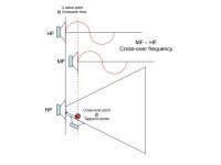
I made a drawing to explain, but here is the reasoning behind it. If we would look and High-mid, we should cross at the highest frequency possible to make it easier to handle for the HF driver BUT ALSO low enough to keep the MF drivers (4") hooked in. If we would take the crossover point as the "center" of the tap, we would have the following advantage;
4 - At crossover point there is 1 frequency that is the exact crossover point BUT, the mid driver rolls of just BEFORE the crossover point, while the HF driver comes in BEFORE the crossover point and will max AFTER the crossover point. That means we wil have a small frequency band where both drivers will be active, THUS over this frequency band the mid driver (which taps in) needs to support all these ferquences WITHIN this band. That means that the tap point will start at the HIGHEST combined frequency (shortest wavelength) and end at the lowest combined frequency (longest wavelength). So the tap supports the entire combined area. SEE FIGURE 1
Now we have set the center of the tap, we need to figure out the start and end point of the tap. The start is the lowest frequency we want both drivers to be active. Than, we need to know the highest frequency as the end (or last point in the path of the horn towards the mouth) of the tap. SEE Figure 2.
5 - Same goes for the low-mid TAP, which will be further towards the mouth and will be based on the combined low-mid frequency area. SEE ALSO figure 2.
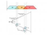
I tried this principles on paper as an example and ended with FIGURE 3.
- I have a 1" HF, a 4" MF and an 8 " LF
- I have set High-Mid crossover at 1kHz
- I have set Mid-Low crossover at 400 Hz
First start with High-Mid since the HF is the start on the horn. ¼ wavelength of 1kHz will be 86 mm. I took 19 mm (tap diameter) as a starting point for the tap (seems to be a frequently used diameter). This would mean that the highest combined frequency would have a ¼ wavelength of 86 mm - 19 / 2 mm = 76,5. This will result in the highest frequency being 1124 Hz.
Second High-Mid ¼ wavelength of the lowest combined frequency. This will be 86 + 19 / 2 mm = 95,5 mm. This results in the lowest combined High-Mid of 900 Hz.
6 - So bandwidth where High-Mid drivers combine will be 900 - 1124 Hz (with 19 mm tap diameter, centered at 86 mm from the throat of the horn)
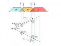
Now we do the same for Mid-Low. 400 Hz crossover will have a ¼ wavelength of 215 mm. If I would take 60 mm diameter for the Mid-Low tap (2 of them for a 8" LF will result in an acceptable compression), this would result in highest Mid-Low of 465 Hz and lowest of 351 Hz. So the combined bandwidth for the Mid-Low will be from 351 - 465. (with a tap of 60 mm centered at 86 + 215 = 301 mm from the throat of the horn)
SEE FIGURE 3 for details.
Hope you get want i would like the explain here.
Million dollar question - DOES THIS MAKE SENCE. if not where did I go wrong.
It would be a very simple model to calculate your own unity horn. You could also start with high / low frequency of both frequency bands and end with the tap start and end point. It's just calculating the other way around.
An excell sheet is on its way, not to complicated.....
b.t.w. if i look at a previous picture of the internals of a Danley unity (VERY smooooooth comment added with picture) it looks like 86 mm would be kind of the same as the Danley.
kind regards,
Frans Wessels
Well, my 2 cents of thoughts;
As I am not the expert here, I read this thread and found it very helpful. In trying to get my hands around this animal and kind of inspired by the last post, I tried to visualize tap points details.
Please your comments on the following;
As I want to build and use a unity horn in my "portable PA" combined with a tapped horn as a sub, I guess I can start with;
1 - Since tapped subs don't go much higher than 200 Hz (and that seems to be stretching it) AND 4" or 5" mids in the Unity horn don't reach this low, I need to build a 3-way unity. Let's say 1", 4" and 8".
Now where to put the tap points. My starting thoughts where:
2 - We combine low & mid AND mid & high. Since we use a 3 way system we have 2 "combined frequency bands", being at low-mid crossover and mid-high crossover. The rest of the spectrum is always single driver area. SO, we need to place these 2 area's at the point in the horn where the wave's of both drivers are in sync. ANYWAY NOT at ½ wavelength (100% cancelation). So at the same point or 1 wavelength apart would be "ideal". 1 wavelength will be to long so, we could go for ¼ wavelength (as described in more articles.
3 - So I go for ¼ wavelength distance between the 2 drivers.
I made a drawing to explain, but here is the reasoning behind it. If we would look and High-mid, we should cross at the highest frequency possible to make it easier to handle for the HF driver BUT ALSO low enough to keep the MF drivers (4") hooked in. If we would take the crossover point as the "center" of the tap, we would have the following advantage;
4 - At crossover point there is 1 frequency that is the exact crossover point BUT, the mid driver rolls of just BEFORE the crossover point, while the HF driver comes in BEFORE the crossover point and will max AFTER the crossover point. That means we wil have a small frequency band where both drivers will be active, THUS over this frequency band the mid driver (which taps in) needs to support all these ferquences WITHIN this band. That means that the tap point will start at the HIGHEST combined frequency (shortest wavelength) and end at the lowest combined frequency (longest wavelength). So the tap supports the entire combined area. SEE FIGURE 1
Now we have set the center of the tap, we need to figure out the start and end point of the tap. The start is the lowest frequency we want both drivers to be active. Than, we need to know the highest frequency as the end (or last point in the path of the horn towards the mouth) of the tap. SEE Figure 2.
5 - Same goes for the low-mid TAP, which will be further towards the mouth and will be based on the combined low-mid frequency area. SEE ALSO figure 2.
I tried this principles on paper as an example and ended with FIGURE 3.
- I have a 1" HF, a 4" MF and an 8 " LF
- I have set High-Mid crossover at 1kHz
- I have set Mid-Low crossover at 400 Hz
First start with High-Mid since the HF is the start on the horn. ¼ wavelength of 1kHz will be 86 mm. I took 19 mm (tap diameter) as a starting point for the tap (seems to be a frequently used diameter). This would mean that the highest combined frequency would have a ¼ wavelength of 86 mm - 19 / 2 mm = 76,5. This will result in the highest frequency being 1124 Hz.
Second High-Mid ¼ wavelength of the lowest combined frequency. This will be 86 + 19 / 2 mm = 95,5 mm. This results in the lowest combined High-Mid of 900 Hz.
6 - So bandwidth where High-Mid drivers combine will be 900 - 1124 Hz (with 19 mm tap diameter, centered at 86 mm from the throat of the horn)
Now we do the same for Mid-Low. 400 Hz crossover will have a ¼ wavelength of 215 mm. If I would take 60 mm diameter for the Mid-Low tap (2 of them for a 8" LF will result in an acceptable compression), this would result in highest Mid-Low of 465 Hz and lowest of 351 Hz. So the combined bandwidth for the Mid-Low will be from 351 - 465. (with a tap of 60 mm centered at 86 + 215 = 301 mm from the throat of the horn)
SEE FIGURE 3 for details.
Hope you get want i would like the explain here.
Million dollar question - DOES THIS MAKE SENCE. if not where did I go wrong.
It would be a very simple model to calculate your own unity horn. You could also start with high / low frequency of both frequency bands and end with the tap start and end point. It's just calculating the other way around.
An excell sheet is on its way, not to complicated.....
b.t.w. if i look at a previous picture of the internals of a Danley unity (VERY smooooooth comment added with picture) it looks like 86 mm would be kind of the same as the Danley.
kind regards,
Frans Wessels
Attachments
Last edited:
Your experiments don't take into account the effects of crossover filters.Has anyone else tried this experiment or have an explanation as to what is going on?
"Synergy" is the result of many combined aspects in concert.
Your experiments don't take into account the effects of crossover filters.
"Synergy" is the result of many combined aspects in concert.
Yes, I agree 100%. The crossover shifts the phase relationship. The idea behind the experiment was to actually measure the distance between the drivers acoustically in order to have an estimate of what the ideal phase shift would be for different frequencies in order to help design the crossover. The surprising thing to me was that the estimated distance based on cancelation was much larger than the physical distance I would have measured (e.g. based distance between the ports or even based on distance between the driver cones).
I've read pretty much this whole thread and folks talk with confidence about the distance between the mid and CD but I haven't seen any reference to measuring it based on the acoustical cancelation so was just curious if someone else tried it.
The only explanations I can think of...
(1) the location where the cd and mid "combine" is not where I think it is and so measuring the distance along the wall of the wave guide or down the axis is not the right path length. What is the "right" way to measure this distance?
(2) the bandpass chamber in front of the mid presumably induces a phase shift. What is the expected behavior? If it introduces a shift then the cancelation point is no longer a half-wavelength.
- Home
- Loudspeakers
- Multi-Way
- Suitable midrange cone, for bandpass mid in Unity horn.