again - EM in nonmagnetic metallic conductors is extremely Linear - Skin/Proximitty/Eddy Current loss is Linear - just not "simple" integer coefficient in s
Actually, it is related to current slew rate. All the big switchmode guys work out some extrapolated dissipation formula's, but they do not care about distortion, just dissipation.
Edit: to be even clearer, it is related to the absolute value of the current slew rate.
jn
Last edited:
George, the discussed paper shows pickup of 13 kHz frequency. Either very poor amplifier (demodulation) or poor instrumentation. Names do not count.
My guess is consistent with both you and George. They did not control loops, and they picked up neutral currents from something that was pulling a 13 KHz current from the neutral conductor in the building.
Variable frequency motor drives can certainly do that. We use them for water pumps, we use them for HCAV fan drives. In both cases, we are trying for about a 1 degree C control, and a bang bang control cannot support that.
George, as I said, that table is an ampacity chart. When the wire resistance of a 12 gauge has doubled, it's still only 3.4 milliohms per foot. Bad for a run of #12 romex, of no concern in an 8 ohm speaker circuit.
jn
1st order the loss should be Linear - when you get heating coupling thru tempco to give time varying R then you can have some harmonic distortion production
I assume all practical XO inductors are order(s) of magnitude more massive than voicecoils so their dT and dR are much smaller
any refs to this |dI/dt| effect would be good
I assume all practical XO inductors are order(s) of magnitude more massive than voicecoils so their dT and dR are much smaller
any refs to this |dI/dt| effect would be good
Last edited:
From the looks of it, that wafer thin pc board has lots of copper on the back. The coils flat to the board will have lower inductance and will go resistively non linear at close to half or a third of the intended crossover frequency.
Sheesh, don't they read Maxwell, or even lenz?
jn
Thats highend for yah ....
")
any refs to this |dI/dt| effect would be good
It's actually quite simple. The eddies are related to the rate of change of the field. That occurs during the current zero crossing, in both the positive and negative directions of a sine. The dissipation is proportional to the absolute value of the cosine.. It can never go negative.
It's obvious by simple inspection.
edit: be careful, I'm not talking about integrated loss, I'm talking about time dependent loss.
I'm working on a test solenoid as we type..The ITER fusion guys have a similar problem, but their solenoid is 30 feet tall and about 24 feet wide.
My solenoid is about 2 inch ID, using what appears to be #10awg magnet wire. And, room temp.
jn
Last edited:
George, the discussed paper shows pickup of 13 kHz frequency. Either very poor amplifier (demodulation) or poor instrumentation. Names do not count.
Now that you mention freq.
One more bell ringing that should have attracted their attention: The ‘mysterious’ frequencies are not the same in all screenshots
In Fig.6.10.d ~ 45kHz
In Fig.6.10.f ~ 13kHz
In Fig.6.11.a and Fig. 6.15.a ~ 28kHz
I can not read the freq scale of the FFTs
Pavel, have you noticed with older DSOs aliasing effects, showing on the screen signals of much lower frequency (and unstable amplitude) than the real input?
VFDs as jn suggests maybe the offender. And they can spit-out noise much higher in freq than that (MHz)
poor amplifier (demodulation)
You mean the driving amplifier?
Demodulating the HF signal picked-up at the input or through the feedback network from the output?
George
I suggested once that a speaker designer (drivers and systems) use the German made ceramic/ferrite white color cores for winding the speaker XO coils on them. Because they were very linear over a wide freq range and could take very high power levels (currents) and stay linear. he tried them and told me they cost less than the air cores he used and had lowered the distortion measurably from his speakers.
I never see them used... wonder why? Building and maintaining Q vs freq is important to proper XO operation.
[no I dont remember the mfr name]
Thx-RNMarsh
I never see them used... wonder why? Building and maintaining Q vs freq is important to proper XO operation.
[no I dont remember the mfr name]
Thx-RNMarsh
Last edited:
yes it is. Very tempting. But the ceramic/ferrite core is excellent and that is why I wonder why they are not universally used - at least in high-end.
The Q of the inductor holds up much better than air core or even laminated iron. Just do a Q vs freq test and if it isnt near 90 degrees at and near the XO freq the over-all response will not be what you predict it to be. From test experience, they rarely are at 90 degrees (pure L) even at the 1kHz they are spec'ed at. And, if you use them at any other freq than 1KHz the phase angle is very different.. even in air core coils. You actually have to test them for Q and L at the freq they are to be used.
Thx-RNMarsh
Pavel, have you noticed with older DSOs aliasing effects, showing on the screen signals of much lower frequency (and unstable amplitude) than the real input?
Hi George,
this is a shot on the target!!
Yes, I have noticed the same problem. With DSO analysis, I have "measured" quite high spectral line below 15kHz when analyzing voltage on long link cable with AM radio RFI pickup. I could not believe my eyes so I used an audio band FFT system with 48kHz BW. No spectral line in audio band then! And much higher dynamic range of the audio band analyzer, more than 130dB, compared to 60-70 dB of the DSO. The DSO "measured" a spectral line below 15kHz with amplitude of some -40dBr. It was nothing but aliasing error, lack of input anti-aliasing filter.
Regards,
Pavel
Thank you for the confirmation.
I asked because I have noticed it in the past and I am cautious ever since.
I think that these investigators may have the same problem:
RF noise picked up by the created test loop, which shows as signal below 100kHz due to aliasing at their DSO.
Jn
This is for you, regarding foil inductors ect (your beloved in depth analysis & simulation of e.c.):
http://alexandria.tue.nl/extra2/200511789.pdf
George
Attachments
Last edited:
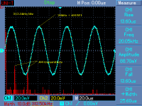
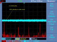
George, I have succeeded to dig out some of my older measurements of RFI pickup. The plot at 312.5kHz/div is correct and shows spectral lines of local AM transmitters. However, the second plot in 31.25kHz/div is wrong and audio analyzer FFT showed no lines in audio band. One might suggest 15.625kHz of TV row frequency, but it was not the case (verified by another instrument). The DSO line was close to 14kHz and it was an aliasing error. Probably the other lines in that plot were wrong as well.
In my experience, it is often problem when the author of the paper is not experienced in measurements as well and if someone else is performing the measurements. There is a temptation to find out sensational conclusions where they are not and it is very easy to make a mistake or to misinterpret plots.
In my experience, it is often problem when the author of the paper is not experienced in measurements as well and if someone else is performing the measurements. There is a temptation to find out sensational conclusions where they are not and it is very easy to make a mistake or to misinterpret plots.
Attachments
Last edited:
Really easy to skip all the crappy coils and go active.
Why? full active speakers i have heard don't deliver , they only deliver in theory ...
Last edited:
Why? full active speakers i have heard don't deliver , they only deliver in theory ...
Yes, it is quite easy to design and implement a poor active speaker too.
I find no difficulty in putting theory into practice with DSP based active crossover and EQ.
Passive crossovers are highly limited in controlling load presented by drivers.
Way too much time goes into thinking about what is happening on the dark side of speaker transducers rather then working with what comes out of them on the light side in using them most effectively.
Transfer function at voice coil leads is not transfer function of acoustic output.
With any amplifier and any transducer worth using in a speaker system very little information is lost to noise and non-linear distortion. Amplitude and phase of spectral components are merely rearranged in the acoustic output.
No can do JC..
Let's stick to stuff you'll understand, eh?
jn
The force is strong with this one.
Nice. About 15 years ago I made superconducting gradient coils for the 4 tesla MRI here. It was fun at that time to learn all about MRI's. The issue I also had to deal with was the fact that I made the coils using superconductors, so the surface conductivity which causes eddies is somewhat "high".. The copper outer shell of the supers also increases conductivity about two orders of magnitude at 4.5 kelvin. The wire I used was a 6 around 1 cable, so it also limited my high speed (frequency) operation to 6/7ths of the cable's capacity, as skinning keeps the current constrained to the outer 6 wires when I slew it fast. The inner conductor will not carry current until the slew rate drops below about half an ampere per second. If the wire is capable of 1400 amperes dc, I can ramp it to 1200 amps in a quarter second, supply voltage limited.....the last 200 amperes requires 400 additional seconds.Jn
This is for you, regarding foil inductors ect (your beloved in depth analysis & simulation of e.c.):
http://alexandria.tue.nl/extra2/200511789.pdf
George
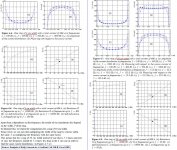
If you go to page 9, in a nutshell: I hilited in red the salient part.
Quote:
Eddy currents cause undesirable disturbances in the gradient field. Moreover, the presence of eddy currents will increase the resistance of the coil, resulting in a higher energy dissipation. Meanwhile, the self-inductance will decrease, resulting in the need for a smaller voltage supply
End quote
When considering an inductor, the actual terminal voltage is from the equation:
V = LdI/dt + IdL/dt + IR
We are all familiar with LdI/dt and IR, but IdL/dt is typically neglected, as is the eddy dissipation portion of R.
The lenz effect means that a conductive object will try to reduce the inductance of the system by rejection of the time varying magnetic field. That is evident in the L vs F scans I put in my gallery.
The eddy dissipation is proportional to the absolute rate of change of the magnetic field.
edit: Unfortunately, it appears that his software doesn't give us the terms we need for modelling the resistance and inductance vs time. Again, this is how the switchmode guys deal with it as well. Neither are interested in the harmonic distortions, just the dissipations.
jn
Last edited:
The force is strong with this one.
Yes, but it was a cheap shot.
John Curl, you have my apology. I am sorry for dissing you in that manner.
John
Why? full active speakers i have heard don't deliver , they only deliver in theory ...
Complete commercial products? How about amps and active/digilal crossovers of your choice? If theory doesn't deliver you need new engineers not a new theory.
- Status
- Not open for further replies.
- Home
- Member Areas
- The Lounge
- John Curl's Blowtorch preamplifier part II