You don't need to wary about that phase dip with TMC, it could come close to -180 degree without stability problem. To meliorate that dip add capacitor in serie with TMC resistor, or bridge the TMC caps with small one, but in this case you are losing some gain at 20 kHZ.
BR Damir
Exactly, I did put in a capacitor in series with the TMC resistor and managed to have the phase dip not exceeding -145 deg. by paying a minor price of THD-20k gone from 3.0 ppm to 3.1 ppm.
Exactly, I did put in a capacitor in series with the TMC resistor and managed to have the phase dip not exceeding -145 deg. by paying a minor price of THD-20k gone from 3.0 ppm to 3.1 ppm.
By the way, what's new with your 200 W CFA?
By the way, what's new with your 200 W CFA?
My plan is to complete my current VFA design, which is a 200 watter with 3EF OPS, bing simulated for 150V/uS SR, THD-20 3ppm @8R/200W or 3.5ppm @ 4R/400W, then order PCBs for both and build them together. Hopefully I can see them compete side by side by the end of this year.
... I found in my simulation ...from the output node instead of the left side of the Tian Probe...
Hi
For a "pure" Cherry compensation, the Tian probe after the output and before the Cherry capacitor is the correct place and actually all you need to examine.
The outer loop can look deceptively stable, as you and Damir have both noticed.
For a scheme like Damir's with both Miller and Cherry compensation the situation is not so easy.
I said a few days back that Damir's illustrated position was not theoretically correct but I wasn't sure how much difference that would make in practice.
I suspect Damir's unexpected result is the result of this incorrectness.
The correct place for the probe is within both loops.
Because Damir has a push pull VAS the correct loop needs to be checked with a balun to separate the differential and common mode components.
I have just built the simulation for this and should have results soon, maybe a bit delayed by nice BBQ weather.
Best wishes
David.
Last edited:
Hi
For a "pure" Cherry compensation, the Tian probe after the output and before the Cherry capacitor is the correct place and actually all you need to examine.
The outer loop can look deceptively stable, as you and Damir have both noticed.
For a scheme like Damir's with both Miller and Cherry compensation the situation is not so easy.
I said a few days back that Damir's illustrated position was not theoretically correct but I wasn't sure how much difference that would make in practice.
I suspect Damir's unexpected result is the result of this incorrectness.
The correct place for the probe is within both loops.
Because Damir has a push pull VAS the correct loop needs to be checked with a balun to separate the differential and common mode components.
I have just built the simulation for this and should have results soon, maybe a bit delayed by nice BBQ weather.
Best wishes
David.
David, I hope you enjoyed BBQ weather, and when back behind your PC maybe you can comment my simulation attempt of local Miller compensation. I am not sure if this tell us more abouth stability.
BR Damir
Attachments
My plan is to complete my current VFA design, which is a 200 watter with 3EF OPS, bing simulated for 150V/uS SR, THD-20 3ppm @8R/200W or 3.5ppm @ 4R/400W, then order PCBs for both and build them together. Hopefully I can see them compete side by side by the end of this year.
Have you seen my attempt of 200 W/8R, 400 W/4R VFA amp, never built this version, just 100 W TT amp?
BR Damir
Thanks, David. And BBQ=
") . Can you point me to the thread please?
. Can you point me to the thread please?
No, I have not. You have too many amps for me to followHave you seen my attempt of 200 W/8R, 400 W/4R VFA amp, never built this version, just 100 W TT amp?
BR Damir
. Can you point me to the thread please?Thanks, David. And BBQ=
No, I have not. You have too many amps for me to follow
Oh sorry, I forgot to insert the link, here it is. http://www.diyaudio.com/forums/solid-state/216780-tt-amp-200w-8ohm-701w-2ohm.html
... when back behind your PC maybe you can comment my simulation attempt of local Miller compensation. I am not sure if this tell us more ...
Hi Damir
The overall loop gain has contributions from the Cherry loop that you showed earlier and from this Miller one.
It is not yet clear to me how the contributions combine.
A bit complicated because there is feed-forward and other non-ideal effects.
It is educational to look at the Miller Loop, as you have, and then alter the Cherry capacitor (C8) as you did in post #456.
The altered Cherry capacitor has a major impact on the Miller loop.
A smaller Cherry capacitor pushes more gain into the inner Miller loop.
This probably explains your results, but we want to understand this interaction better.
I think Middlebrook's Extra Element Theorem shows how to work out the interaction in a way that is understandable.
But I don't understand Middlebrook sufficiently well yet.
His stuff is available freely on the web and is excellent, have you seen it?
Also his understudy Vorperian has a book called "Fast Analytical Techniques".
The local library has a copy and I will read more when they reopen on Monday.
In the meantime we can examine the actual loop gain rather than try to calculate it from the different contributions.
I will continue to work on that.
Best wishes
David
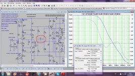
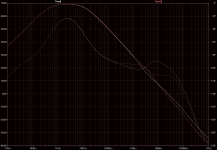
Miller loop. Tian is with 100pF C8 Cherry capacitor. Tian2 is with 47 pF. Circuit is Damir's OIC version but with simplified, one bank OPS to save space.
Attachments
Last edited:
Hi Damir
The overall loop gain has contributions from the Cherry loop that you showed earlier and from this Miller one.
It is not yet clear to me how the contributions combine.
A bit complicated because there is feed-forward and other non-ideal effects.
It is educational to look at the Miller Loop, as you have, and then alter the Cherry capacitor (C8) as you did in post #456.
The altered Cherry capacitor has a major impact on the Miller loop.
A smaller Cherry capacitor pushes more gain into the inner Miller loop.
This probably explains your results, but we want to understand this interaction better.
I think Middlebrook's Extra Element Theorem shows how to work out the interaction in a way that is understandable.
But I don't understand Middlebrook sufficiently well yet.
His stuff is available freely on the web and is excellent, have you seen it?
Also his understudy Vorperian has a book called "Fast Analytical Techniques".
The local library has a copy and I will read more when they reopen on Monday.
In the meantime we can examine the actual loop gain rather than try to calculate it from the different contributions.
I will continue to work on that.
Best wishes
David
Miller loop. Tian is with 100pF C8 Cherry capacitor. Tian2 is with 47 pF. Circuit is Damir's OIC version but with simplified, one bank OPS to save space.
Hi David,
I will try to understand the compensations interaction better from the Middlebrook's Extra Element Theorem, but that could be over my head, to rusty after so long years from University.
But I think I started to better understand that interaction looking at Bode plot of internal compensation loops. You help a lot and thank you for your time.
I used a kind of TCP on this amp and now I am back. Adding just a resistor(R35) to the ground and creating combination of OIC and TPC(how to call that – OITPC) and Miller compensation(no shunt compensation here, Waly should be satisfied) THD20k decreased for 8 dB.
Best wishes
Damir
Attachments
...I used a kind of TCP on this amp and now I am back. Adding just a resistor(R35) to the ground and creating combination of OIC and TPC(how to call that – OITPC) and Miller compensation(no shunt compensation here, Waly should be satisfied) THD20k decreased for 8 dB.
Yes, I think TPC works well for OIC as well as Miller.
This is in accordance with Bode and is one of the central ideas of my article in Linear Audio.
I include TMC as a type of TPC.
And I also think you and Waly are correct, shunt is usually sub-optimal.
Nice to have the ideas in the article confirmed, I would be worried if your results did not match my theory
But the AD797 uses some shunt compensation and seems to be OK.
So need to quantify the trade-offs better.
Should have results tomorrow. Bedtime here.
Best wishes
David
Guru Zan, I think this effect is similar to what I observed with 'pure Cherry'. ie Smaller Cherry caps initially give better 'inner' (your Bode Return Ratio) stability while making the 'outer' main loop more wonky. But as the system nears instability (with smaller Cherry caps), both 'inner' & 'outer' loops become worse.The altered Cherry capacitor has a major impact on the Miller loop.
A smaller Cherry capacitor pushes more gain into the inner Miller loop.
I'd like to do more work on this and also investigate the real significance of decoupling the VAS emitter resistor but need to get several beach bum issues out of the way.
May we beg you to use a white background on your plots?Miller loop. Tian is with 100pF C8 Cherry capacitor. Tian2 is with 47 pF. Circuit is Damir's OIC version but with simplified, one bank OPS to save space.
Also, where is the probe for these curves? Did you post a pic with it's position earlier?
___________________
Damir, I've used 2 pole Cherry with success in real life in the last Millenium. It often provided better stability too. This is cos the 'pure Cherry' Return Ratio (with enhanced VAS 2 EF2) is 2nd order with the single 'pure Cherry' cap. Making the demanded gain 2nd order (which is what you do when you use 2 pole Cherry) means the Return Ratio becomes nicely 1st order and closer to Cherry's intentions.
But today, I favour the simpler 'pure Cherry'.
The big advantage of 'pure Cherry' over 2 pole Cherry is that it allows substantial PSR improvement by the addition of 1 ceramic cap. This is C1 in #4 of the tpc-vs-tmc-vs-pure-cherry thread.
Decoupling the VAS emitter allows good stability with 'pure Cherry' for those versed in the art
For most amps, PSR is an important factor in THD performance .. one which is usually ignored by the usual SPICE analysis ... ie a lot of distortion is fed back from the power supply rails due to poor PSR.
Alas, I only know how to do this useful trick on VFAs with LTP & current mirror i/p
Last edited:
Also, where is the probe for these curves? Did you post a pic with it's position earlier?
___________________
Damir, I've used 2 pole Cherry with success in real life in the last Millenium. It often provided better stability too. This is cos the 'pure Cherry' Return Ratio (with enhanced VAS 2 EF2) is 2nd order with the single 'pure Cherry' cap. Making the demanded gain 2nd order (which is what you do when you use 2 pole Cherry) means the Return Ratio becomes nicely 1st order and closer to Cherry's intentions.
But today, I favour the simpler 'pure Cherry'.
The big advantage of 'pure Cherry' over 2 pole Cherry is that it allows substantial PSR improvement by the addition of 1 ceramic cap. This is C1 in #4 of the tpc-vs-tmc-vs-pure-cherry thread.
Decoupling the VAS emitter allows good stability with 'pure Cherry' for those versed in the art
For most amps, PSR is an important factor in THD performance .. one which is usually ignored by the usual SPICE analysis ... ie a lot of distortion is fed back from the power supply rails due to poor PSR.
Alas, I only know how to do this useful trick on VFAs with LTP & current mirror i/p
Look here http://www.diyaudio.com/forums/solid-state/243481-200w-mosfet-cfa-amp-47.html#post3771847
...I think this effect is similar to what I observed with 'pure Cherry'...
Yes, but a bit less clear at the moment whereas I actually do understand how the two loops in Cherry interact.
Hence my confidence that you only need to probe at the one point for Cherry.
Hope to have results for Damir today and we will see more.
...the VAS emitter resistor...
It is an important point to optimise because not many other opportunities to add a zero, they are valuable!
I think this true for many compensation schemes, not just pure Cherry.
Also, where is the probe for these curves? Did you post a pic with it's position earlier?
Same as the pic in Damir's #465.
of 'pure Cherry' over 2 pole Cherry is that it allows substantial PSR improvement by the addition of 1 ceramic cap. This is C1 in #4 of the tpc-vs-tmc-vs-pure-cherry thread.
I liked that neat trick. Probably possible to extend the idea with an extra RC to add a pole/zero to C1.
Best wishes
David
Last edited:
Should qualify this ..But today, I favour the simpler 'pure Cherry'.
today, I favour the simpler 'pure Cherry' even for enhanced VAS + EF2
Finally
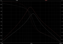
Finally finished the test fixture to see the total loop gain at the VAS.
This combines the Cherry loop and the Miller loop.
Shown is the result for 47pF and 100pF Cherry capacitor C8, in white and pink respectively.
I hope the black is not too much of a problem, it looks the best on my monitor and I am reluctant to alter it.
Just wanted to show the initial results for comment while I think about it more.
The interactions mean that a smaller capacitor does not alter the response in just one direction.
Best wishes
David
Attachments
Last edited:
Finally finished the test fixture to see the total loop gain at the VAS.
This combines the Cherry loop and the Miller loop.
Shown is the result for 47pF and 100pF Cherry capacitor C8, in white and pink respectively.
I hope the black is not too much of a problem, it looks the best on my monitor and I am reluctant to alter it.
Just wanted to show the initial results for comment while I think about it more.
The interactions mean that a smaller capacitor does not alter the response in just one direction.
Best wishes
David
I don't know how you've got it, but it looks stable to me.
Thank you very much for your effort David,
BR Damir
I don't know how
I will post more details once I am sure it's correct
...it looks stable to me.
To me too.
I need to study why low frequency roll off, but the upper frequency area looks believable.
I did a sim with your added 1k shunt resistor and it does show an improvement in stability.
Probably more improvement possible because 1k looks not quite optimal.
Best wishes
David
Need to alter other time constants, I can't place the phase peak from the resistor where I want it.
It hardly moves in frequency as the resistor is altered, Amplifiers are never simple.
Last edited:
I will post more details once I am sure it's correct
To me too.
I need to study why low frequency roll off, but the upper frequency area looks believable.
I did a sim with your added 1k shunt resistor and it does show an improvement in stability.
Probably more improvement possible because 1k looks not quite optimal.
Best wishes
David
Need to alter other time constants, I can't place the phase peak from the resistor where I want it.
It hardly moves in frequency as the resistor is altered, Amplifiers are never simple.
Change what ever you need to get the best compensation.
BR Damir
I need to study why low frequency roll off, but the upper frequency area looks believable.
The low frequency roll-off is due to the power rail RC decouple to the IPS and the 1k load in the IPS cascode.
At low frequency they act as a divider for the Tian probe injection.
Need to think about what that means for loop gain but it seems my differential Tian probe implementation works fine.
Now I can accurately test whatever Damir, Richard Lee (or anyone else) comes up with.
Next step is a full Middlebrook2006 probe on the differential fixture and see if it makes any difference.
Best wishes
David
- Home
- Amplifiers
- Solid State
- 200W MOSFET CFA amp