Hi, ofcourse they are different way, and different difficulty, and different number of other components parameter that will take the effect, like heat, stability, and supplies.Ontoaba, its all very interesting but you should be aware that excellent figures can be had using simple tweaked Self topology and new compensation techniques like Edmonds TMC. Is all that added complexity really worth it ??
You need to know how Edmond TMC works for first, and then how Candy's EC works. This is depend on the designer which one to choose. If it is not patented I am sure will place it on my mosfet amps. Because it is the simplest way to get its multi functions. All the problem is choosing the mosfet that not heavily affected by heat, no need linear or ultra fast mosfet. Just ask a company for the mosfet and they will make it done. Also most mosfet already small heat effect.
With linear OPS, VAS stage is more easy to built because don't need big gain for feedback, just make it as linear as possible.
I would surely like to see someone building that and measuring it in real life. How much do the simulated and real life THD values differ with exact component matching? Can 0,00000x figures become something like 0,000x figures in real life?
Hi, ofcourse, there is a mining tool company built many of it and claims 300ppb(0.00003%)THD at full power and 500ppbTHD at 20kHz full power. If a simulation using good modeiling, it will close or at least similar to real with reasonable error.
Last edited:
Take a close look at Candy's US patent 5,892,398, issued April 6, 1999. Look closely at his Figure 2, particularly the output stage where the error correction is located. You will see that it is essentially the same as my implementation of HEC for MOSFETs that I published in the JAES in the early 1980s. You can even see that he largely used the same means of compensating the HEC - look at how R43 is shunted by the series combination of C79 and R80 in the load of the HEC differential error amplifier Q50. Note also his use of very similar compensation in the emitter circuit of the complementary error amplifier, C84 and R83.
There are of course some minor differences, such as his use of a CFP driver for the output MOSFETs and his use of a bootstrapping circuit for much of the output stage circuitry. Overall, it is largely the same as my implementation of HEC. It is unfortunate that nowhere in this first patent does he reference the prior art of Hawksford and me.
Note that Candy has another patent, 6,798,285, dated September 28, 2004, wherein he finally does cite the prior art of Hawksford and me, but that patented circuit is not true HEC, and just involves gobs of negative feedback.
It has always been a bit unclear to me which of the circuit approaches were used in which of the Halcro amplifiers.
Cheers,
Bob
Hi, Bob.
Yes, I see, that EC is very similar with your implemented Hawksword's. But looks like Candy make it to have different function. It has ability to cancels major non linearity, minor non linearity, and major circuit timing error in different and independent tuning places(components). Not correctly shown at the patents, he only showing its major function to cancel major non linearity, just like what your EC do, and with only this it only reach 4ppm maximum tweak at 1 kHz, and if it is only the function, your EC is doing better than his, but he added at least 2 another functions. Also my bumps only need 2bjt to cancel major non linearity with worse results, but this alone is not enough.
Umm. I think halcro using both that candy's patents well implenented in it. The 2nd patent is improvement for amplifier in 1st patent. I don't know why he patented such things (in 2nd patent), because with correct EC in patent 1 it already could reach few hundred ppb THD scale.
It has some problems into 2 Ohm.
Umm..Hi, I don't know what you mean, but if you have any problem with Candy's EC, This EC is not belong to me, it is Candy's. You may investigate it with sim, it has good way to cancel non linearity that you could use it in somewhere else.
I am currently working with different one, not finished, yet, but it has very good starting results.
Attachments
Hi, ofcourse, there is a mining tool company built many of it and claims 300ppb(0.00003%)THD at full power and 500ppbTHD at 20kHz full power. If a simulation using good modeiling, it will close or at least similar to real with reasonable error.
Could you supply reference to this mining company ?? I can believe such figures may be possible with small signal stages but not on a power amp.
A couple of years back I experimented on achieving very low THD figures, my lab rat was a pioneer M91 which had very good acclaimed figures. I found the company only told small lies, and one channel of the amp far exceeded all my expectations. At 100 watt 8 ohm it could do 0.0022 THD 20khz. After many hours and tweaks trying to better this I gave up although simulations showed that figures with the tweaks should be much better. The limitation must be a physical one, ie circuit layout part imperfections etc. Id say the M91 is about on par with the Halcro, looking at the figures obtained by stereophile but now look at the schematic, half the complexity, is it really worth the trouble going so complex when you get to such figures. Maybe the pioneer with better layout could do better....
Now you say 500ppb THD at 20kHz full power, sorry thats just impossible. Just taking into account physical limitations I would say that company is pulling some very thick wool over peoples eyes.
Could you supply reference to this mining company ?? I can believe such figures may be possible with small signal stages but not on a power amp.
Try with google, there are many, this is the key: minelab halcro
Their claims, sorry my mistake, it is 100ppb, not 300ppb like I mentioned before. Distortion: <–126dB (<500 parts/billion) up to 20kHz at full power output, all harmonic-distortion orders. THD: <–140dB (<100ppb) at 1kHz. Intermodulation products: all <–126dB relative to power output for sum of 19+20kHz tones, each delivering 100W into 4 ohms, or at peak power. May be he is not good at this claim, but you could take the advantage from his patents for your benefit.
Sorry I can't simulating M91 output stage with that unknown IC. It says non switching circuit type II with the IC. I wonder, is that M91 sounds better after your TMC tweak?
Last edited:
Try with google, there are many, this is the key: minelab halcro
Their claims, sorry my mistake, it is 100ppb, not 300ppb like I mentioned before. Distortion: <–126dB (<500 parts/billion) up to 20kHz at full power output, all harmonic-distortion orders. THD: <–140dB (<100ppb) at 1kHz. Intermodulation products: all <–126dB relative to power output for sum of 19+20kHz tones, each delivering 100W into 4 ohms, or at peak power. May be he is not good at this claim, but you could take the advantage from his patents for your benefit.
Sorry I can't simulating M91 output stage with that unknown IC. It says non switching circuit type II with the IC. I wonder, is that M91 sounds better after your TMC tweak?
I simulated the M91 without the benefit of that switching IC and it still does very good. The non switching seems to only benefit frequencies above 10 Khz and I recall something to that effect said in its patent. I didnt do TMC tweak on it as Edmond hadnt shown how to calculate working values at the time but now that youve proposed it maybe it could be implemented here. The raw M91 taking out preamp and other unnecesary signal loops sounds mighty fine to my ears. I compare apples to apples, raw amp to raw amp.
Thanks Ill do some reading up on that minelab halcro.
is it really worth the trouble going so complex when you get to such figures.
I just get lower distortion figures in my current work, and going to the next step for speed up and smoothing crossover. But I am just think about it is really worth?

When some very good equipments just with 90dB S/N ratio or even worse to 80dB. For this reason may be 0.002% THD is more than enough.
Then at recording environments and total equipment noise might much higher than that. So, why people just try to get 0.000x% THD, IMD, and noise figure. May be it is not really worth, and again why they trying to get that 0.000x% for 20kHz, that most of us can't really hear it, and is part of heavily filtered band in recording.
Is it really worth? Thanks that was good question, and I hope someone could give some answer.
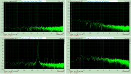
This is my current work last results. Just want to show that with EC we could get 10times lower THD easily.
Attachments
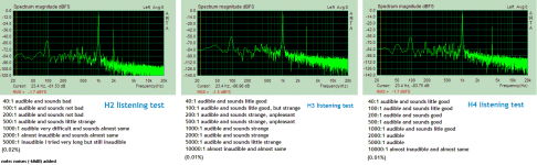
After doing few things simple with ARTA, and it is most easy. I got that most recording has noise around -60dB and -70dB. Also harmonic distortion 0.01% is difficult to compare by listening.
May be we could say that 0.01%THD is the margin, and 0.005% for IMD because it has more spread spectrum may be twice maximum.
Then half of that, an amplifier with less than 0.005% THD and 0.0025% IMD is perfect and amplifier with less than 0.0025% THD and less than 0.001% IMD is just too much, and that figures are useless when compared to 0.0025% THD and 0.001% IMD. Anyone agree or disagree?
Attachments
Last edited:
Anyone agree or disagree?
I cannot say yes or no
because "the devil is in the details"
some amps with THD <0,001% IMD<0,01% sounds bad
some with 4% THD sounds good.
For me good factor for good sound are descending high order odd harmonics from FFT spectrum.
I changed my mind last time: I believe that SS amps with low THD might sound good
Yes there are many things happened, THD and IMD is just two of them. An amplifier with 4% THD isn't only amplifier, but it attached with effect box at 4% FX volume. In this case it will depend on how the FX change the sounds.
Ofcourse an amplifier with less than 0.01% THD has its purity from FX, if the other things not make it worse. Looks like that the other things are more dominant.
Ofcourse an amplifier with less than 0.01% THD has its purity from FX, if the other things not make it worse. Looks like that the other things are more dominant.
Schematic for Halcro's DM38 wanted
A friend of me is user from a Halcro stereo power amp model DM-38, serial No 2400152. There is sometimes some trouble.
At one channel the sound is sometimes more softly and reproduction with a bit less high frequency shares. Definitely to rule out is the speaker cable, the speaker and the cinch lead/connectors as a source of error.
This means, the amp must be disassembled for troubleshooting and measuring check.
Therefore I need a detailled service manual include schematic diagram and circuit description (theory of operation).
In the meantime Halcro don't exist in the old kind. The developer isn't longer emloyed at the currently owner.
From where I can order the service documentation to this device?
Thank you very much for advices.
P.S. check out in this case also the posts from #2598 about
http://www.diyaudio.com/forums/solid-state/89023-bob-cordell-interview-error-correction-260.html
Last edited:
- Status
- This old topic is closed. If you want to reopen this topic, contact a moderator using the "Report Post" button.
- Home
- Amplifiers
- Solid State
- halcro amplifier