.....hope nothing else damaged......
I remember reading early in thread that Andrej said it would be capable of output short if no input signal is present,
 for your setup.
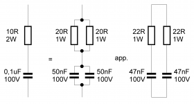
I attach picture from earlyer this thread about zobel network. If you break the two onboard, it could be repaired external either temporary or permanent with the 10ohm/100nF config.
Attachments
Did you guys note 45 ppm THD20 at 100 Wrms/4 Ohm, I am really pleased.
It depends on the complexity of course. I think you can get similar thd result with SSA BIGBT HP

I remember reading early in thread that Andrej said it would be capable of output short if no input signal is present,
I attach picture from earlyer this thread about zobel network. If you break the two onboard, it could be repaired external either temporary or permanent with the 10ohm/100nF config.
Hi BYRTT,
there are two 20R resistor . both have some brown marks but one of them is open. I have soldered a 20R through hole resistor over the open 20R and have powered up both channels and tested it. The dc offset, input , output bias current are all ok.
NOw playing music through test speakers and sound clean and nice.There appear to be ground loop problem in both channels that i am troubleshooting now.
Is there any possibility of failure in the C of the zobel??
What is the effect of malfunction zobel circuit ?
thanks again
kp93300
1- Not really.1-Is there any possibility of failure in the C of the zobel??
2-What is the effect of malfunction zobel circuit ?
2- Possible oscillation.
Groundloop see post #2534 point 3 and 6, think point 3 make your solution......There appear to be ground loop problem in both channels that i am troubleshooting now.
Is there any possibility of failure in the C of the zobel??
What is the effect of malfunction zobel circuit ?
thanks again
kp93300
Don't think you can destroy cap in zobel, the resistor is the fuse there.
I remember earlyer in thread that VSSA is tested to run without the zobel, it only sits there to protect HF oscilation with complicated loads (especially exsotic speaker cables). Example if you run simple 1-3 meter 0.5-1,5mm solid speaker cable into a full range speaker, VSSA is staple without zobel, but one is on own responsibility when not following standard setup.
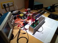
Immersion heaters I would say! What is the impedance on those things LC?
All heaters together in parallel 4 Ohm plus 0,12 uH inductance in series.
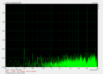
At 20 kHz it comes to 4,015 Ohm, so I set 20,1 Vrms to get exactly 100,6 Wrms for spectrum measurements and result is 45 ppm THD20
Hi Andrej very impressing control and specs you get with new diy-AP setup, i guess it is very fun/learning/satisfying and can be saved as knowledge librarary. Later tell if the tuning is more or less audioable.
If you think VSSA module could benefit this tuning, would it be possible to pay for the service done by you. Example i send you a mono module, you tune and post for VSSA owners, i pay and you send module return.
If you think VSSA module could benefit this tuning, would it be possible to pay for the service done by you. Example i send you a mono module, you tune and post for VSSA owners, i pay and you send module return.
Today's play with MIC, measurements showed 45 ppm THD20, 100 Wrms/4 Ohm, slowly getting there. Half THD than with Miller only from post #3052.
Just a hint.
We use PICO scope 4262. It makes it possible to do a FFT at up to 200KHz.
If you run a 20KHz source, you will be able to see:
2. harmonic 40KHz.
3. harmonic 60KHz.
4. harmonic 80KHz
and so on.
With the system right now you will only see the 2. harmonic when measuring at 20KHz.
- Sonny
Yes, my Tek is showing all that and more on its spectrum analyzer but to only -80 dB. Does Pico scope goes deeper?
It is around -100dB.
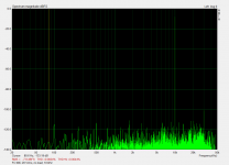
Today's 10 kHz measurements:
1. Input signal spectrum
2. Output signal 20 Vrms, no load
3. Output signal 20 Vrms on 4 Ohm
Third harmonic is the same as present in input signal. While loaded at 100Wrms/4 Ohm, only second and fourth are higher, third unchanged. Distortions are only 64 ppm the same as simulated on very much complex CFA designs.
With better input signal the amp itself would present also lower THD. Interestingly First One has even harmonic character, although these are very low, that can sound nice and pleasant.
First One is now ready to enter the market.
Attachments


Last edited:
- Home
- Vendor's Bazaar
- VSSA Lateral MosFet Amplifier