Hi guys 
First One with Miller compensation, real measurements 10 W/8 Ohm and 25 W/4 Ohm, plus intermodulation 13+14 kHz")
First One with Miller compensation, real measurements 10 W/8 Ohm and 25 W/4 Ohm, plus intermodulation 13+14 kHz
Attachments

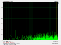
So, now few serious spectrum comparison measurements on First One with only 10 pF standard Miller compensation.
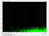
One graph shows 20 Vrms no load connected, next graph shows the same output 20 Vrms on 4 Ohm load, meaning 100 Wrms/4 Ohm. Diferences between the two are very small but hopefully enough to compare them with other type of compensations coming in next days.
One graph shows 20 Vrms no load connected, next graph shows the same output 20 Vrms on 4 Ohm load, meaning 100 Wrms/4 Ohm. Diferences between the two are very small but hopefully enough to compare them with other type of compensations coming in next days.
Attachments

Richard, If i remember well, you had ordered two L.C.'s VSSA. Did-you had time to try them, and, if yes, can-you give-us some listening impressions ?Looking to try a couple pcb with vssa circuit to test. Any pcb - thru hole only available? where? How to get latest and greatest?
Looking to try a couple pcb with vssa circuit to test. Any pcb - thru hole only available? where? How to get latest and greatest?
LC -- who makes ZxR audio card?
Thx-RNMarsh
Hi Richard
Please do not bother with VSSA, just wait a little and buy First One in group buy which will start in January 2014.
Some drastic tests are performed nowadays in my lab, so the First One modules will be set to very high performance as spectrum graphs will confirm it too.
In post #3031 the link to sound card specs is provided if you just click on word "here".
Regards L.C.
Dear Lazy Cat,
Confess this is Alien Technology from an UFO fallen on Slovenian mountains and that you reverse-engineered
BTW, how does it sound with and without cap?
Best of lucks,
M.
Hi, no alien technology here just properly made PCB layout with minimal parasitics impedances (very very important) and optimized parts values, that's all.

First One HF compensation
Today's work, transformed HF compensation to true Cherry, so compensating caps connected directly from the output to VAS bases. The results are shown bellow.
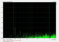
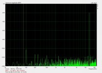
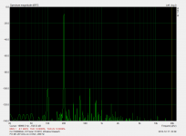
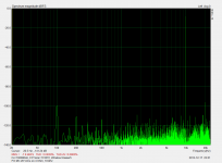
First graph is spectrum of the input 0,82 Vrms sine signal fed to the First One module.
Second graph is spectrum of the output 20 Vrms sine signal, no load, Miller HF compensation.
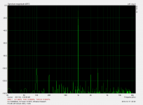
Third graph is spectrum of the output 20 Vrms sine signal, no load, Cherry HF compensation.
Résumé of all measurements is that there's practically no difference whatsoever between the two. In spite of so close performance I noticed a little better HF stability by the Miller compensation, so Miller stays in.
Today's work, transformed HF compensation to true Cherry, so compensating caps connected directly from the output to VAS bases. The results are shown bellow.
First graph is spectrum of the input 0,82 Vrms sine signal fed to the First One module.
Second graph is spectrum of the output 20 Vrms sine signal, no load, Miller HF compensation.
Third graph is spectrum of the output 20 Vrms sine signal, no load, Cherry HF compensation.
Résumé of all measurements is that there's practically no difference whatsoever between the two. In spite of so close performance I noticed a little better HF stability by the Miller compensation, so Miller stays in.
Attachments

I need a bit of clarification.
1) the manual indicates maximum power supply of 45 V.
My power supply is 43.5 V to 46.5 V dc. , depending on the time of the day .
Is 46.5 V dc acceptable?
2) LC indicate a 120 mv bias adjustment between TP1 and TP2. With cold heatsink, my bias is 98mv and climb to 130 mv after 15minutes . Is this acceptable ? output dc is 3 mv
thanks
kp93300
HD at 20KHz signal not better with Cherry ?Résumé of all measurements is that there's practically no difference whatsoever between the two. In spite of so close performance I noticed a little better HF stability by the Miller compensation, so Miller stays in.
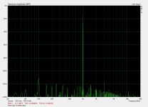
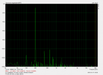
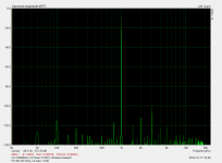
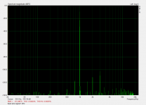
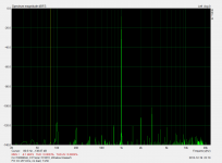
First One Miller HF compensation, spectrum of 100 W/4 Ohm, 20 kHz.
Second harmonic (40 kHz) 80 dB below the signal (20 kHz).
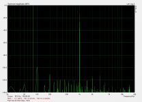
1. Input signal 890 mVrms, 20 kHz
2. Output signal 20 Vrms, 20 kHz
3. Output signal 20 Vrms/4 Ohm, 20 kHz
PSRR is -92 dB at 100 W/4 Ohm, very good for CFA.
Damping is also very high since there's absolutely no difference in output voltage (-7,7 dB rms on both 2nd and 3rd graph) when 4 Ohm load is connected.
So 96 ppm THD20 at 100 W/4 Ohm, pleased with the results, since these are real world measurements, not simm.
Second harmonic (40 kHz) 80 dB below the signal (20 kHz).
1. Input signal 890 mVrms, 20 kHz
2. Output signal 20 Vrms, 20 kHz
3. Output signal 20 Vrms/4 Ohm, 20 kHz
PSRR is -92 dB at 100 W/4 Ohm, very good for CFA.
Damping is also very high since there's absolutely no difference in output voltage (-7,7 dB rms on both 2nd and 3rd graph) when 4 Ohm load is connected.
So 96 ppm THD20 at 100 W/4 Ohm, pleased with the results, since these are real world measurements, not simm.
Attachments


Last edited:
Hi, First One is a power amplifier module, a logical step forward from VSSA to universal CFA amplifier module. More power and better overall quality compared to VSSA.
Size of the module is 50 x 100 x 40 mm and will be ready made to the last part ie. detail.
Output power 180 W/8 Ohm, 320 W/4 Ohm
Coming out in January 2014
Regards, L.C.
Size of the module is 50 x 100 x 40 mm and will be ready made to the last part ie. detail.
Output power 180 W/8 Ohm, 320 W/4 Ohm
Coming out in January 2014
Regards, L.C.
Hi guys, yes definitely commercial amplifier module with a price target bellow 80 EUR, hopefully.
Put together my own "Audio Precision" system just to optimize THD with choosing a proper compensation method, most probably combined one, TMC or MIC. Today already got extra -8 dB THD20 compared to just plain Miller comp, really enjoying playing with my new toy hehe
Put together my own "Audio Precision" system just to optimize THD with choosing a proper compensation method, most probably combined one, TMC or MIC. Today already got extra -8 dB THD20 compared to just plain Miller comp, really enjoying playing with my new toy hehe
Nice, Andrej. Very nice.
I discovered in this forum all those fancy comp names (TMC, Cherry etc.) for something i did during Jurassic, when necessary, with a very stupid approach ;-)
- Do not add charge at HF in sensitive points, like VAS collector (comp signal kept at output don't hurt).
- Try all the way i can imagine to minimize the phase turn at 20KHz between signal and feedback.
This said, if comps can improve numbers, i'm not sure it really change sonic. I hope you will share what you'll learned at those floor levels. And that your new measurement toy will not depart-you too much from listening and listening again
Promised?
About PSRR, did-you filter the rails for input stage + VAS ? (Regulation or cap multiplier)
Very nice.I discovered in this forum all those fancy comp names (TMC, Cherry etc.) for something i did during Jurassic, when necessary, with a very stupid approach ;-)
- Do not add charge at HF in sensitive points, like VAS collector (comp signal kept at output don't hurt).
- Try all the way i can imagine to minimize the phase turn at 20KHz between signal and feedback.
This said, if comps can improve numbers, i'm not sure it really change sonic. I hope you will share what you'll learned at those floor levels. And that your new measurement toy will not depart-you too much from listening and listening again
Promised?
About PSRR, did-you filter the rails for input stage + VAS ? (Regulation or cap multiplier)
Help !!
While testing i accidentally short the output and burnt the 20R0 resistor next to the output
Can i replace with this :
MCPWR10FTFQ0200 - MULTICOMP - RESISTOR, 2010, 20R 1%, 0.75W | element14 Malaysia
Are these 2010 size chip resistor and are these 20R . What is the rating ?
thanks
kp93300
While testing i accidentally short the output and burnt the 20R0 resistor next to the output
Can i replace with this :
MCPWR10FTFQ0200 - MULTICOMP - RESISTOR, 2010, 20R 1%, 0.75W | element14 Malaysia
Are these 2010 size chip resistor and are these 20R . What is the rating ?
thanks
kp93300
Looked in the pre BOM and it says 0,75W SMD2010, so your link seems right. It belongs to the 2 times RC zobel network at output, and for quick repair it should be possible to make these two RC networks 47nF/20ohm off board with TH pieces.Help !!
While testing i accidentally short the output and burnt the 20R0 resistor next to the output
Can i replace with this :
MCPWR10FTFQ0200 - MULTICOMP - RESISTOR, 2010, 20R 1%, 0.75W | element14 Malaysia
Are these 2010 size chip resistor and are these 20R . What is the rating ?
thanks
kp93300
- Home
- Vendor's Bazaar
- VSSA Lateral MosFet Amplifier