Not fuses, but audiophile power circuit breakers! ")
An externally hosted image should be here but it was not working when we last tested it.
He was changing the distribution of interconnect return current. The worse the RCA ground integrity, the more return current goes through the safety bonds.I have a friend who has been dabbling with manufacturing cables, I doubt he is going to make his fortune from this...
I was at his place one day when he changed a set of interconnect cables for another which were visually identical. For want of a better expression one set sounded a little soft and fuzzy compared to the other. As it happens the more direct sounding pair had the RCA plugs laser welded by a local manufacturing jeweller. The other pair were soldered; identical cables and plugs.
I was simultaneously impressed and depressed that two connections per channel could be so audible.
This was just my observation and the test was sighted, though I didn't know what I was hearing until afterwards.
I love the concept of the sampling bridge. I used one in the early 80's. It was really neat how they created the pulses that turned the bridge on, my first industry exposure to striplines. I also love the input bridges for their ability to clamp at incredible speeds so cleanly.My worst give away ever was a 1963 Lumitron sampling scope. One of the greatest tour de forces of discrete design I ever saw. Used every exotic available, tunnel and snap diodes, gold doped transistors, etc. The sampling head was a GR connected hard line with a diode bridge soldered to the center conductor via holes drilled in the outer conductor and the hold capacitor was the grid capacitance of 6CW4's. The trigger circuit was a tunnel diode one shot that hit the sampler via a snap diode edge enhancer. It had a 25psec/div range in 1963.
Barrie Gilbert is the only person I know that knows the story, it came with a reed/charged line pulse generator predating the 109.
Just use the appropriate flux for the job. Once the intermetallics are formed, you're done.I would be very interested to know your friends exact soldering technique and what brand of phono ( RCA ) plugs he used for this test. What kind of plating on the plugs. Did he clean / scrape / file the wires & plugs before soldering and if so exactly what method before we declare that even soldering is a floored connection method.
I have an unsubstantiated idea that filing down to bare, unplated metal seconds before soldering might be the most ideal method of connection using solder.
Another possible variable is whether he made a good mechanical hard metal to hard metal connection before he applied the solder. i.e. is the solder a third element in the signal path or just a way of covering and protecting a good mechanical joint.
I wonder if you enquired about these possible variables.
mike
When the joints alter the return path for the low level signals.Forgive me for sounding stupid, but how can a few mechanical joints in the home cause so much trouble to a signal which has already passed through quite a few joints in the recording studio or the concert hall? Or do top recording engineers now weld all their cables into fixed configurations? Must make it fun to get them on and off the van when doing on-site recording!
jn
A Small Suggestion...

http://www.newark.com/pdfs/datasheets/PanasonicEW/DS-RELAYS.pdf
TYPICAL APPLICATIONS
Besides telecommunications, measuring
devices, office equipment, computers
and related equipment, DS relays are
also recommended for a broad range of
applications including business devices,
audio systems, and industrial equipment.
I don't know if the contacts are bifurcated, but they do say Ag+Au clad.
These sealed relays are bistable, needing only a momentary coil current, and can have one coil or two coils for set/reset contact positioning.
I bought a handful of these from eBay for $3.00 each but never got around to trying them...they are in a box.....
These relays rely on a permanent magnet somewhere inside to operate the armature....I need to crack one open.
Anyway, my purpose in buying these was to determine if the internal magnet causes sonic mayhem....or not.
Else wise these ought to be a very useful 'non volatile' relay in all kinds of applications, including switched attenuators, source selection, etc...
Dan.
Some interesting reading... http://www.panasonic-electric-works.com/peweu/en/downloads/ds_x61_en_relay_technical_information.pdf
There really are relays designed for very low level signals. These typically have quad bifurcated gold plated cross bar contacts. Older types used long levers to activate the contacts to keep the low level signals away from the coil, as not only is the magnetic field an issue, so is the distortion induced by iron near a signal conductor. That of course varies with the circuit impedance.
http://www.newark.com/pdfs/datasheets/PanasonicEW/DS-RELAYS.pdf
TYPICAL APPLICATIONS
Besides telecommunications, measuring
devices, office equipment, computers
and related equipment, DS relays are
also recommended for a broad range of
applications including business devices,
audio systems, and industrial equipment.
I don't know if the contacts are bifurcated, but they do say Ag+Au clad.
These sealed relays are bistable, needing only a momentary coil current, and can have one coil or two coils for set/reset contact positioning.
I bought a handful of these from eBay for $3.00 each but never got around to trying them...they are in a box.....
These relays rely on a permanent magnet somewhere inside to operate the armature....I need to crack one open.
Anyway, my purpose in buying these was to determine if the internal magnet causes sonic mayhem....or not.
Else wise these ought to be a very useful 'non volatile' relay in all kinds of applications, including switched attenuators, source selection, etc...
Dan.
Some interesting reading... http://www.panasonic-electric-works.com/peweu/en/downloads/ds_x61_en_relay_technical_information.pdf
Last edited:
Max, we have been using relays like this for decades. The JC-80, Parasound PlD 2000, and the Parasound JC-2 use similar relays. They work OK, but Silver-on-Silver Shallco switches actually sound better. I try to minimize or avoid relays with my best efforts. Of course, they are better than many other alternatives.
10 mA was enough for me to see changes.
The RCA was a follow up on another thread. I had mentioned 1.5 volts dc into a 10K load for an overnighter changed the performance of and RCA cable.
I tried it last night on about 2' of freshly stripped wire and 10mA, didn't see any oxidation on either end.
I tried it last night on about 2' of freshly stripped wire and 10mA, didn't see any oxidation on either end.
I didn't use freshly stripped wire. I used an old RCA cable. The cable connector and the test jig connectors had different metal finishes. I examined the point of contact with a 10 diopter magnifier. The big variable is humidity. But thanks for actually doing a test. Do you have a setup to measure the distortion?
If anyone really cares I can repeat the test and take pictures.
Last edited:
How did you examine the point of contact without disconnecting the cable?I didn't use freshly stripped wire. I used an old RCA cable. The cable connector and the test jig connectors had different metal finishes. I examined the point of contact with a 10 diopter magnifier. The big variable is humidity. But thanks for actually doing a test. Do you have a setup to measure the distortion?
If anyone really cares I can repeat the test and take pictures.
jn
How did you examine the point of contact without disconnecting the cable?
jn
Ed, there is no voltage drop anywhere in the cable at 150uA so there is no driving force for surface oxidation. This is not at all similar to anodic corrosion which cost me and my neighbors lots of money. Seems the ground source heat pump ground and "grouind" had a couple of volts difference, when they pulled up the 1100' of well pipe some was gone.
Again an extraordinary claim from an experiment with lots of uncrossed t's.
Also when you make "connections" how do you control for the inevitable breaking through the surface and having a clean metal to metal contact.
JN, Ed - some fun regarding cable testing. You both might get a point.
Can't do that. You've lost control of the current paths.
jn
How did you examine the point of contact without disconnecting the cable?
jn
I look at the point of contact before "Fixing" the cable and after. I also run a measurement. There are slight changes.
Ed, there is no voltage drop anywhere in the cable at 150uA so there is no driving force for surface oxidation. This is not at all similar to anodic corrosion which cost me and my neighbors lots of money. Seems the ground source heat pump ground and "grouind" had a couple of volts difference, when they pulled up the 1100' of well pipe some was gone.
Again an extraordinary claim from an experiment with lots of uncrossed t's.
Also when you make "connections" how do you control for the inevitable breaking through the surface and having a clean metal to metal contact.
We are not talking about micro diodes or any such. Nor any effect on the conductor surface. It is at the point of contact for the connectors that changes when you "Restore the Electrons" (One silly claim for the process)
Yes, whenever you disconnect and reconnect any cable of the type you clean the connections. We have been over that. Many claims of cable improvement just come from cleaning. The issue here was not that the ends got cleaner but that one end appeared dirtier.
I've found a highly effective philosophy is to be always willing to do the overkill - make something considerably 'better' than normal thinking would suggest is necessary. If that creates a decent jump in quality then slowly back off in the overkill factor until one just perceives an audible change happening - an optimum for the current stage of refinement has been found.
Obviously, this is a tedious, long-winded process, painful to the max if one takes it seriously all the time - it's the 'ideal' way of doing things. But using that approach to a reasonable level has taught me many things, certainly much more than reading all the standard material.
Obviously, this is a tedious, long-winded process, painful to the max if one takes it seriously all the time - it's the 'ideal' way of doing things. But using that approach to a reasonable level has taught me many things, certainly much more than reading all the standard material.
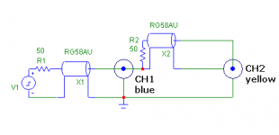
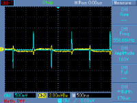
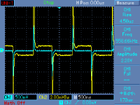
JN: No - think it over. Blue channel is an inductive voltage drop on cable shield. Yellow channel shows what is in fact at the end of the coaxial cable - it is not that simple as voltage drop across the shield. That's how coax works. The other cable is a poor audio non-coax structure, then the shield current reflects in output voltage. Many 'audiophile' cables behave this way.
Obviously, this is a tedious, long-winded process, painful to the max if one takes it seriously all the time - it's the 'ideal' way of doing things. But using that approach to a reasonable level has taught me many things, certainly much more than reading all the standard material.
Respectfully, really these sort of posts are getting tedious, at least for me. Specific examples of what you do and what the impact is would liven things up just a tad.
Regards,
Rob.
Quite literally.
As the hydrogen nuclei are spinning in/out of their natural range anyway, one might say they're also doing the tango.
- Status
- Not open for further replies.
- Home
- Member Areas
- The Lounge
- John Curl's Blowtorch preamplifier part II