Hi guys/Owen,
? about insulators for LME49830 wire amp.
1) For the LME49830, do I need a insulator/thermal compound, (is the Ohmite HS isolated?) if so, what part #
2) LatFET, my HS's are not isolated from ground, so I need insulators, part number to use pls.
3) Owen do you have any LME49830 to sell me? Mouser/Digikey out of stock til Dec'13. Need up to 4 for the pcb's I have on order. I can add extra $ to my payment to you.
Thx
Rick
Hi Rick,
You definitely will need an insulator between the heatsink and the LME49830 as the tab is at V- potential, and the heatsink is tied to ground.
I just use a standard adhesive back TO-220 isolator like the one listed on the LPUHP BOM, and cut it to size. Don't use the one listed in the PSU BOM as it's electrically conductive
As for the output devices, I know some people use Keratherm red with good results, but I tend to just use thin mica insulators with thermal grease, which has always worked well for me in the past.
Here's a link that might be of interest if there is any left:
http://www.diyaudio.com/forums/vend...therm-red-86-83-isolators-247-1-ea-stock.html
I do have a 8 LME49830 ICs left over from the previous GB but I didn't offer them up as they are too thick to be shipped in a standard bubble pack. Since you're in Canada, it's not really a big deal so you're welcome to pick up 4 if you'd like. I think they go for $7 on Digikey, so let's call it $25 for 4 of them.
I also owe you an email, but I'm a bit backlogged until I get things sorted out with the orders. I will get back to you though.
Cheers,
Owen
Owen, thx for your FB & offering me some LME49830, perfect I'll take 4 of them, pls add to my order of pcb's.
Take your time, I am in no rush, still have to order part & I am working on my Si4770 layout this week, want to get it out for fab ASAP. Decided to add a S/PDIF tx using a DIT4192.
Rick
Take your time, I am in no rush, still have to order part & I am working on my Si4770 layout this week, want to get it out for fab ASAP. Decided to add a S/PDIF tx using a DIT4192.
Rick
Lateral FET Amp
Hi Guys,
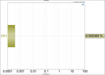
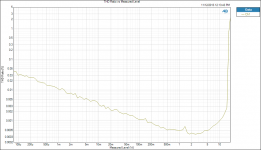
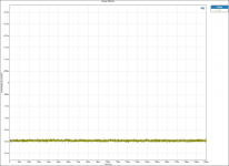
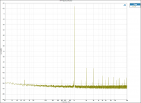
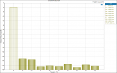
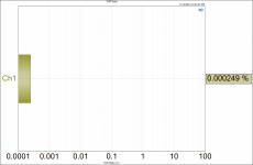
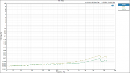
Attached are the measurements for the high power lateral FET amp.
These were all taken with dual regulated supplies feeding the amp. The PSU V2 was used at +/-24V to power the LME49830, and a LT1185 based supply fed the mosfets with +/-20V.
Power is obviously limited in this setup, but I was mostly just curious to see what the amp could do with lower noise supplies.
All measurements are done into an 8 ohm load, and the first set were done at 450mA bias.
I will also post a second set done at 900mA bias to show the improvement in distortion.
Cheers,
Owen
Hi Guys,
Attached are the measurements for the high power lateral FET amp.
These were all taken with dual regulated supplies feeding the amp. The PSU V2 was used at +/-24V to power the LME49830, and a LT1185 based supply fed the mosfets with +/-20V.
Power is obviously limited in this setup, but I was mostly just curious to see what the amp could do with lower noise supplies.
All measurements are done into an 8 ohm load, and the first set were done at 450mA bias.
I will also post a second set done at 900mA bias to show the improvement in distortion.
Cheers,
Owen
Attachments
-
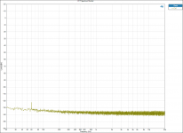 FFT Spectrum Monitor no input.png101.8 KB · Views: 824
 -
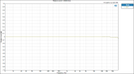 FR 1W 8R.png65.5 KB · Views: 796
 -
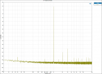 FFT Spectrum Monitor 1W 8R.png103.4 KB · Views: 797
 -
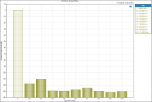 Distortion Product Ratio 1W 8R.png48.7 KB · Views: 782
 -
 THD Ratio 1W.png66.3 KB · Views: 762
 -
 THD Ratio vs output power 8R.png74.1 KB · Views: 180
 -
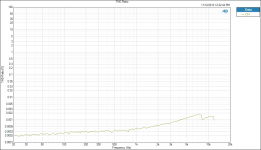 THD Ratio v freq.png61.1 KB · Views: 172
 -
 DC offset - No Input.png78.9 KB · Views: 142
 -
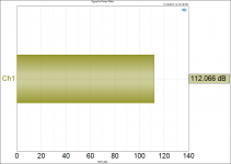 Signal to Noise Ratio 10W 8R.png45.5 KB · Views: 142
 -
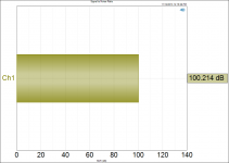 Signal to Noise Ratio 1W 8R.png45.2 KB · Views: 163
Nice, I now have similar power supply needs for the two LME A/AB amps I already have built... something like +/-15V on the output side.
On the input side, would you recommend one PSU per amp, or should one be ok feeding the input of two LME's? Will be using two separate regulated 3A supplies for the outputs.
The two Class A/AB's will be powering a pair 8 Ohm Scan Speak woofers and the LPUHP's a pair of Mark Audio A7.3...
Paul
On the input side, would you recommend one PSU per amp, or should one be ok feeding the input of two LME's? Will be using two separate regulated 3A supplies for the outputs.
The two Class A/AB's will be powering a pair 8 Ohm Scan Speak woofers and the LPUHP's a pair of Mark Audio A7.3...
Paul
Impressive observational skills Chris!
No oven yet... but some of the stuff I've been working on makes me wish I had one!
As for the bulbous solder joints, I blame my rushing, and the fact that I ran out of my favorite Cardas solder and am stuck using this odd radio shack stuff which isn't the best.
I had the solder wick out and started to clean up some of the joints, but then decided I'd have plenty of time to do that after I shipped out everyone's goodies
Thanks again to everyone here for all the support and positive comments, and I'm looking forward to shipping these out and having people build them all up!
Cheers,
Owen
I've got a toaster oven here half hacked to pieces waiting for me to install an SSR and hook it up to a little arduino controller to make a cheap SMT oven
With these regulator boards ... I've got a story and a question
1. I had been toying with the idea of looking at using a snubber between the rectifiers and the transformer for some DSP board layouts that I'm toying with. Looking at your measurements it seems these regulator's PSRR really take care of the issues at lower freq, above 1MHz on the datasheet the PSRR starts to drop away ... I wonder if for that freq range the issues are really more related to inductance in the connection from reg to load and the load's input decoupling. Just wanted to say thanks again for these measurements ... you've got me thinking and cleared my mind of a few issues that are sometimes hard to understand the magnitude of their impact in the real world.
2. I am in need of a dual +ve regulator. Hacking these to create dual +ve rails is going to be a no-go from my cursory glance right? Best case use the on board +ve reg and flick the diodes around and use the rect+filter section of the -ve half with an external regulator (say a super-reg). It's really not possible to isolate the two halves of this board though is it, the gnd plane will be connected at the output of the rectifiers? I'm just putting the ideas down now because I know someone else will be wondering too probably.
On the LME49830 amp ... I've had a quick glance at the DPS600 measurements (I've only got access to my dropbox on my phone though at the moment so small screen only) so these new regulated supplies are a small improvement on the DPS600 performance in noise floor and THD+N though in that case I think we're comparing 450mA to 600mA bias with the DPS600 tests so I'm allowing for that in the way I read these. One question, Owen, the distortion product ratios ... those values include noise, right?
Cheers,
Chris
Si4770 layout this week, want to get it out for fab ASAP. Decided to add a S/PDIF tx using a DIT4192.
I was looking at an interface board design this morning before work, I was just about to start drawing up a part layout for the DIT4192 but alarm went off saying time to go and put an end to that
Nice, I now have similar power supply needs for the two LME A/AB amps I already have built... something like +/-15V on the output side.
On the input side, would you recommend one PSU per amp, or should one be ok feeding the input of two LME's? Will be using two separate regulated 3A supplies for the outputs.
The two Class A/AB's will be powering a pair 8 Ohm Scan Speak woofers and the LPUHP's a pair of Mark Audio A7.3...
Paul
Hi Paul,
One supply shared by two amplifiers would be fine for the input stage. The LME has a very constant current draw, so there will not be any crosstalk issues with a setup like that.
As for the supply voltage, I would really suggest running it quite a bit higher than +/-15V for the output stage. At that rail level, the LPUHP will actually be the more powerful amplifier into 8 ohms, so you'd be better off using all LPUHP amps and reaping the performance advantage.
If I were to properly do a setup like the one you're describing, I would use something like a pair of LT1084 regulators set to roughly +/-28V along with a PSU V2 set to +/-32V for the front end. That will give you roughly 40W of output, and you can bias pretty high without dissipating too much power, while still having significantly more headroom than an LPUHP.
If you really don't need the power, then going with all LPUHP amps would be the better option. With a good 100VA transformer, you can expect about 18W of output before distortion rises above 1% thanks to the new regulators and the fact that the output buffers don't start current limiting until about 190-200mA RMS each. You can also push the supply voltage a little higher to +/-19 volts is you really want to push the limits.
Cheers,
Owen
I've got a toaster oven here half hacked to pieces waiting for me to install an SSR and hook it up to a little arduino controller to make a cheap SMT oven
I'm jealous! Let me know how it turns out and I might give it a go. I've always wanted to make one, but never got around to it. I can only imagine the amount of time it would have saved me by now!
With these regulator boards ... I've got a story and a question
1. I had been toying with the idea of looking at using a snubber between the rectifiers and the transformer for some DSP board layouts that I'm toying with. Looking at your measurements it seems these regulator's PSRR really take care of the issues at lower freq, above 1MHz on the datasheet the PSRR starts to drop away ... I wonder if for that freq range the issues are really more related to inductance in the connection from reg to load and the load's input decoupling. Just wanted to say thanks again for these measurements ... you've got me thinking and cleared my mind of a few issues that are sometimes hard to understand the magnitude of their impact in the real world.
Indeed, I would imagine the performance at and above 1MHz would be more down to decoupling and layout than the actual regulator itself. The TPS regs are extremely good at rejecting rectification noise and harmonics, and those really are the major culprits to noise in the audio band.
I think for higher frequencies, shunt regs probably have an advantage at keeping noise out of the rest of the system (eg, decoupling noisy elements from other supplies) but even then it depends on their bandwidth, layout, decoupling and grounding.
2. I am in need of a dual +ve regulator. Hacking these to create dual +ve rails is going to be a no-go from my cursory glance right? Best case use the on board +ve reg and flick the diodes around and use the rect+filter section of the -ve half with an external regulator (say a super-reg). It's really not possible to isolate the two halves of this board though is it, the gnd plane will be connected at the output of the rectifiers? I'm just putting the ideas down now because I know someone else will be wondering too probably.
I had a closer look at the layout, and I don't think it's feasible to make it into a dual positive reg as the GND plane connects between the final two output caps and the GND terminal. You might be able to do it by cutting the output connector end of the board off, and then cutting the entire PSU in half, but it would be risky as you may short out the layers when you cut the board in half.
What I did realize though while looking at it is that I need to go back and change the BOM to use electrically isolated thermal pads for these regs as the tab on the positive reg is not at ground potential!!!
I several TPS7A4700 regulator mini boards and I can send you a few with your order if you can solder them!
On the LME49830 amp ... I've had a quick glance at the DPS600 measurements (I've only got access to my dropbox on my phone though at the moment so small screen only) so these new regulated supplies are a small improvement on the DPS600 performance in noise floor and THD+N though in that case I think we're comparing 450mA to 600mA bias with the DPS600 tests so I'm allowing for that in the way I read these. One question, Owen, the distortion product ratios ... those values include noise, right?
I was actually expecting more of a difference in terms of noise with the full linear regs, but indeed they aren't much better than the DPS600. The real advantage to the LME49830 based amp is the much higher output potential, and the DPS600 lets you capitalize on that aspect while still keeping noise low.
Unless you really only need 50W or less, then the DPS would be my first choice for a supply.
As for the DPR measurements, my understanding is that they do not include noise with the exception of that which falls into the bands where the AP is looking for harmonics. Usually anything below 130dB is just noise that happens to be correlated with that harmonic at the instant the capture is made. The DPR measurements do not use averaging, so those upper harmonics are bouncing all over the place in real time, and their position is random when I save the graph. I could save three graphs in a row and the 2nd and 3rd harmonics wouldn't budge, but anything higher would be all over the place, varying randomly by 6-10dB.
If higher harmonics are present, then it easily points them out (eg, they are stable and repeatable) but in these cases, the upper harmonics are so close to the noise floor that they are basically one in the same unless you start averaging and finding some correlation. For that you can look at the FFT with the 1kHz tone.
Cheers,
Owen
As mentioned above, but repeated here for clarity:
DO NOT USE THE INSULATORS LISTED IN THE BOM FOR THE PSU!!!!!!!
I mistakenly assumed the GND tab on the regs could be electrically connected to the heatsinks but they cannot! The positive reg's tab is not at true GND potential.
Instead, use the parts listed in the LPUHP BOM for isolating the regulators from the heatsinks. You will need the same hardware (4-40 screw and nut) but you will need an additional plastic shoulder washer for isolating the screw, and a non conductive thermal pad for the reg itself.
I will see if I can get a moderator to fix that attached BOM.
In the meantime, if anyone already placed an order, give me a heads up and I'll toss in a pair of thermal pads and a pair of washers with your boards.
Cheers,
Owen
Would it be possible to get a single post with all of the required BOMs for this GB (BAL-BAL, SE-SE, PSU, etc)?
I just find it frustrating having to look back pages and pages to try to find the BOM I need for a specific board, then having to look back more pages and pages to find the BOM for one of the other boards, and so on, only to have them change later on.
Having one place to look for all of the required information would simplify things greatly.
I have a server I can host the BOMs on indefinitely if needed for free (unlimited storage, unlimited bandwidth), I'm paying for it anyway and might as well help out the community, and I have no plans to shut it down any time in the next decade (been going since '07 if that matters). Just let me know via email if that would help at all.
Last edited:
Indeed, I would imagine the performance at and above 1MHz would be more down to decoupling and layout than the actual regulator itself. The TPS regs are extremely good at rejecting rectification noise and harmonics, and those really are the major culprits to noise in the audio band.
I think for higher frequencies, shunt regs probably have an advantage at keeping noise out of the rest of the system (eg, decoupling noisy elements from other supplies) but even then it depends on their bandwidth, layout, decoupling and grounding.
Yeah for higher freq I think I'll be exploring some of the SMT passive filter solutions out there for what I've got in mind with higher freq it's probably a more appropriate solution than shunt regs ... for clocks and things I think the flea type / buffered voltage reference solutions are all on the cards too because the load isn't very dynamic so low impedance of shunt reg isn't critical ... anyway we digress.
I had a closer look at the layout, and I don't think it's feasible to make it into a dual positive reg as the GND plane connects between the final two output caps and the GND terminal. You might be able to do it by cutting the output connector end of the board off, and then cutting the entire PSU in half, but it would be risky as you may short out the layers when you cut the board in half.
Yeah, I'd rather use two boards and only populate half or roll my own PCB which is what I had in mind but the timing of these coming available is convenient and thought I'd explore the option if it saved time.
I several TPS7A4700 regulator mini boards and I can send you a few with your order if you can solder them!
That might be handy, I've already got a clutch of TPS7A4700 regulator pcbs from iancanada that are pretty handy and I have parts to populate a few more of them but the designs I'm daydreaming about I seem to go for QFN or SOT23 regulators onboard and I think the more critical parts then are passive components and layout between the reg and the load. The input regs are probably less critical really.
As for the DPR measurements, my understanding is that they do not include noise with the exception of that which falls into the bands where the AP is looking for harmonics. Usually anything below 130dB is just noise that happens to be correlated with that harmonic at the instant the capture is made. The DPR measurements do not use averaging, so those upper harmonics are bouncing all over the place in real time, and their position is random when I save the graph. I could save three graphs in a row and the 2nd and 3rd harmonics wouldn't budge, but anything higher would be all over the place, varying randomly by 6-10dB.
If higher harmonics are present, then it easily points them out (eg, they are stable and repeatable) but in these cases, the upper harmonics are so close to the noise floor that they are basically one in the same unless you start averaging and finding some correlation. For that you can look at the FFT with the 1kHz tone.
Cheers,
Owen
That makes sense. Thanks! So differences in higher order harmonics between LME49830 amps with different PSU shouldn't be taken as absolute I guess.
Cheers,
Chris
There are some notes in the BOM worth reading. If you want to build the SE input variant, you need to omit the first two op-amps and their associated parts, and re-select the resistors to get the gain you want for the remaining stage. I'll elaborate on this later in a proper Wiki.
Any chance we can get a quick note on which resistors we should look at for gain? Maybe just attach the schematic of that area of the LPUHP amp and we can work it out ourselves?
Can you point it to me please. The only one I saw, was the one labeled (updated) and I could not see the insulators listed on it.Instead, use the parts listed in the LPUHP BOM
I did find these at Mouser,
951-SPK10-006-00-90
Thanks
Rick
Any chance we can get a quick note on which resistors we should look at for gain? Maybe just attach the schematic of that area of the LPUHP amp and we can work it out ourselves?
The 430R resistor in the LPUHP v2 BOM is marked as the resistor to change to adjust gain. There was a table in the LPUHP v1 BOM that shows 430R being the resistor for 15dB gain and 200R for 21dB gain. In terms of schematic for the input stage, from what Owen's said is it hasn't changed much (at all?) from last version. For a simpler view of it the BAL-SE headphone amp schematic is the same input stage also ... 3 x LME49990 as instrumentation amplifier ...
The change in resistor selection for SE input is more significant (and only needs 1 opamp) but for now best reference is the LPUHP v1 BOM or the SE-SE headphone amp.
Hope that helps
Cheers,
Chris
Hi Guys,
Well, it's the time we've all been waiting for... payment and shipping time!
Everyone on the list will receive a PM by the end of the day today with my email address for Paypal, a copy of the instructions below, and a link to this post. Please wait until you get the actual request to make payment.
The only significant change is that the NTD1 boards have been removed from the order sheet, and I have noted those orders in a separate spreadsheet. I am doing some major rework on that circuit, and I don't want to sell people a bunch of boards and then release a brand new version a month later. I will deal with the NTD1 orders at a later time.
Please follow the instructions below very carefully, as deviating from them makes everything much more difficult for me, and will result in your order being delayed! Please be sure to read all of the instructions before making a payment.
Step 1:
Go to the following shared spreadsheet and confirm your order:
https://docs.google.com/spreadsheet/ccc?key=0AnMLwB9mdXl2dFlBRGZZX1BNZGRSM1FnZGw5V3gyVWc&usp=sharing
You are welcome to make changes to your order by adding or removing boards, or cancel your order entirely by removing your name and order from the list.
The list will automatically calculate your new total, so please make all necessary changes and get your correct total before making payment.
Note that this list is not for new orders, but simply to summarize and track existing orders. If you have a new order to place, please do so on the original list linked in the first post.
Step 2:
Make payment for the total given in the list via Paypal to the email address provided in the PM or email you received.
Be absolutely sure to do the following when you make payment:
1 - Always include your diyAudio username in the "notes" or "message" section
2 - Always include your full address, exactly how you want it written on the envelope, in the "notes" or "message" section.
Step 3:
Check back on the list posted above to see the status of your order in the "paid" or "shipped" column.
All orders will be processed in the same order as payments are received. That means people who pay first, will have their orders shipped first, regardless of the order of the list.
Please do not make order changes on the list after you have made payment. If I see a discrepancy between the payment made and the total listed in the spreadsheet, I will not ship the order until things have been clarified which will result in long delays.
That's all!
If you have additional items with your order, I will include the additional amount to be paid in the note I send to you. This only applies to the few people who bought leftover lateral fets or LME49830 drivers.
Cheers,
Owen
- Home
- Vendor's Bazaar
- "The Wire" Official Boards for All Projects Available Here! BAL-BAL, SE-SE, LPUHP