I designed my board for TO-3 devices because I reclaimed 8 pairs from a crusty old HH V800. Suitable TO-3 devices are still available, as has been pointed out, just not the exact Hitachi ones I used.
Also, TO-218, TO-3P, TO-3PF and TO-247 (the best choice of these) were actually dimensioned to 'replace' TO-3 devices in a flat package and as such could actually be used with my boards too. They can be placed either on top with a heat sink adapter like to TO-3s (less desirable) or underneath directly on the heat sink (best option IMHO).
Thanks for getting back to me Terry, I just wasn't sure if there was an issue with the PM system or not.
The 10R might have saved some transistors for some people, when it turns into a fuse. For others it may just be an annoyance when it fails.
This is why I kept the VAS rail cap at 100uF than 1000uF. With the latter, a 1W 10R resistor or at least a half watt part per rail is mandatory.
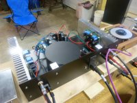
My build sitting on an unfinished home-made case.
I am always guaranteed of good music that comes out of it while waiting for my other case parts.
")
Supercool cabinet man!
I see most guys built the boards that have a little wiggle room. I probably should have started there. Got my DX MKIII fired up today. Pretty stoked. I'll try to get back to this ASAP.
Matter of different tastes I guess. And that's always welcome. Guys like Naf has successfully built the small boards without much problem and they sound same as the other designs, I expect.
Due to the amp's "CFB" nature I tried to integrate it into a small layout as much as I could. My apologies if it bothered you with so little space on it.
Hi Guys,
This has probably been asked, but I have to ask why we continue to design amps that need devices that aren't made anymore. Aren't there devices being made that will work for this type of amp? I love the idea of the amp but there must be some way to make obtainable parts work for it.
Thanks, Terry
All the generic devices are in full production. Some of the "substitutes" used in fact are obsolete. However, it is designed to help the builder make use of whatever parts he/she can source; of course with the expectation to experimentation on his side by himself. Some of the popular audio/superfast transistors have been proven to be villains by some, while others are using them without any problem. This can sometimes happen due to device parameter variation.
Last edited:
Some of us (not everyone) are mosfet or lateral fet fans so you cannot blame us for choosing the ancient parts.
Of course. We have good reasons to be fan of those ancient devices.

I am fan of the topology, not the devices. I would love to use jFETs in the inputs, but had to stick to BJTs due to the unavailability of P-channel jFETs where I live. I'd like to use the 5200/1943 pair, but that still can't be biased as simply as the LATFETs plus there is the second breakdown. Some will use that and that's perfectly okay with guaranteed SSA sonics.
Hi Shaan,
No apology necessary, I'm sure if I had a better printer the boards would have been much easier to use. I started with a bad etching job and then tried to build it using parts from my parts drawers. The caps I used were physically too large and made it very difficult to reach anything with a probe. That is what caused me to short out the VAS and blow everything. I need to start over and just buy parts that fit the board design. This design needs to be built with care. Something that I didn't do. Sorry if I came off as complaining. That was not my intent. The only reason I asked about the MOSFETs is that I hadn't realized how difficult they were to come by until I did a search the other day. I had four of them left over from an Elliot P101 that I built back in 2007 so I used those. When I decided that I should start over anew, I went looking for the MOSFETs and saw that they were disappearing. Again, sorry if I came off wrong.
Blessings, Terry
Last edited:
Hi Everyone,
this is my new peeceebee.
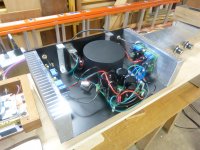
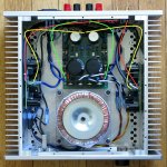
as you can see, I'm using the Mr. Evil/PMI capacitance multiplier psu. I'm really loving it and it would be my favorite amp except that I have a hum I cannot solve. to me, it sounds like the typical 50-60hz hum.
I originally built without the transformer cover, but it has not helped. since my first version I have also increased the size of the cabinet. the hum is audible maybe 2 feet from my woofer but not from my listening position. However, if I put the peeceebee in my bi-amp set-up, the hum becomes audible from listening position. none of my other amps have this characteristics. I've swapped out power supplies, preamps, the ground loop breaker, and have tried many variations of ground connections, but nothing seems to impact hum at all. even when I assemble full enclosure, no change.
the hum is acceptable (did I mention this is my favorite amp!) until I put in the bi-amp rig. Has anyone else experienced this with the peeceebee? Any recommendations?
Kind regards,
freeman
this is my new peeceebee.
as you can see, I'm using the Mr. Evil/PMI capacitance multiplier psu. I'm really loving it and it would be my favorite amp except that I have a hum I cannot solve. to me, it sounds like the typical 50-60hz hum.
I originally built without the transformer cover, but it has not helped. since my first version I have also increased the size of the cabinet. the hum is audible maybe 2 feet from my woofer but not from my listening position. However, if I put the peeceebee in my bi-amp set-up, the hum becomes audible from listening position. none of my other amps have this characteristics. I've swapped out power supplies, preamps, the ground loop breaker, and have tried many variations of ground connections, but nothing seems to impact hum at all. even when I assemble full enclosure, no change.
the hum is acceptable (did I mention this is my favorite amp!) until I put in the bi-amp rig. Has anyone else experienced this with the peeceebee? Any recommendations?
Kind regards,
freeman
Attachments
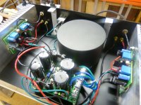
Hi very nice build/setup looks good. Maybe this purpose ends as air, but then tried as not a reason. Do they big washers on output devices touch anything and make any unintended ground loop. In middle of amp board you have empty ground point, try connect it to both VAS heatsinks by leads. Have you tried different voltage drops on CM PSU board. Last guess, those lytics feedback caps are 2,2mF, if under 1mF here exchange with at least 1mF (those caps size do change amps behavior in lows, just where you have misbehavour)......except that I have a hum I cannot solve.....
Last thing if color coding from transformer production is gone wrong, try exchange spade "AC1"/"AC2" or "AC3"/"AC4" on CM, but only do this if you have variac to follow current consume at slow voltage rising is normal behavior.Hi very nice build/setup looks good.....
Thanks , BYRTT. I'm in process of changing position of trans and psu to eliminate the grounds that encircle the trans. I failed to mention that I'm using PMI's amp boards which have a convenient ground connection between the small heatsinks that I did not think to use. Thanks for your help. I will report back shortly. Cheers!
Hi Everyone,
this is my new peeceebee.
as you can see, I'm using the Mr. Evil/PMI capacitance multiplier psu. I'm really loving it and it would be my favorite amp except that I have a hum I cannot solve. to me, it sounds like the typical 50-60hz hum.
freeman
Just my guess, the heat sink of one trans of the cap multiplier may have attracted some stray magnetic fields from the trafo and disturbed its function properly since it touches the cover metal. Try to make some distance away from it.
Regards.
Ground Connections
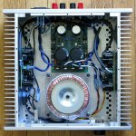
Just for reference, the two pics below show the ground connections in my test chassis. Ideally the two RCA's would not be in one corner, but the chassis was originally made for something else.
I tried to avoid looping any signal or ground wires even partially around the transformer.
Red: Signal Ground. Separated from Power ground by a small ground lifter resistor on the VSSA/PeeCeeBee board.
Yellow: Power Ground. Closest ground connection to the 4700 uFd output caps.
Green: Speaker Return. Closest ground connection to the 10.000 uFd main reservoir caps, and to the rectifier. Bypasses the PSU ground bus where the filter circuit ground connections are made on the PSU board.
There is one ground connection for every power take-off on the PSU board, so other configurations are just as easy.
Attachments
...I'm using PMI's amp boards which have a convenient ground connection between the small heatsinks...
Hi Freeman.
I hope you are returning all the ground wires to the star ground in Pete's PS board and then running one single wire from star ground to chassis earth. This should have a loop-less interconnection in the ground rail.
That connection is a floating pad, to use in case of a common heatsink. A center pin or wire from the heatsink would solder into that pad....I'm using PMI's amp boards which have a convenient ground connection between the small heatsinks that I did not think to use...
It would then have to be connected to another ground point on the bottom of the board, using another wire, depending on the overall grounding scheme.
PeeCeeBee/Through-Hole VSSA Layout, Revised
I finally finished my PeeCeeBee layout revisions (almost exactly 5 months after the first layout). This will make the 4th version of VSSA for me, including one built close to Shaan's original schematic, one close to Version 1.4 of the original design, and the VSSA modules from LC's first Group Buy.
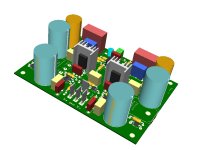
Some small component spacing issues and hole size problems have been fixed, and the circuit board will now accept a wider range of capacitor sizes and VAS heatsinks. This includes a standard U-shape heatsink like the one used in the last version, and the H-shaped heatsink with extra fins I used on the Cap Multiplier power supply board.
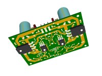
VAS transistors can be mounted on separate heatsinks as shown in the first model pic, or on the main heatsink along with the Latfets, as shown in the second pic. This should allow higher supply voltages, and a little more power per channel.
The circuit board will now accept Renesas Latfets, or the ALF08N/08P. With regard to the Alfets, pads for protection diodes ahve been added.
Aside from that, the original concept is still the same. The circuit board can be built close to Shaan's schematic at the beginning of this thread, or closer to the Version 1.4 schematic. With or without the 10uF parallel caps, with or without the Jfet CCS, input cap or direct coupled. Still single layer.
Conventional through-hole parts only, no exotic or unobtainable parts, and lots of room to experiment, and have fun...
I finally finished my PeeCeeBee layout revisions (almost exactly 5 months after the first layout). This will make the 4th version of VSSA for me, including one built close to Shaan's original schematic, one close to Version 1.4 of the original design, and the VSSA modules from LC's first Group Buy.
Some small component spacing issues and hole size problems have been fixed, and the circuit board will now accept a wider range of capacitor sizes and VAS heatsinks. This includes a standard U-shape heatsink like the one used in the last version, and the H-shaped heatsink with extra fins I used on the Cap Multiplier power supply board.
VAS transistors can be mounted on separate heatsinks as shown in the first model pic, or on the main heatsink along with the Latfets, as shown in the second pic. This should allow higher supply voltages, and a little more power per channel.
The circuit board will now accept Renesas Latfets, or the ALF08N/08P. With regard to the Alfets, pads for protection diodes ahve been added.
Aside from that, the original concept is still the same. The circuit board can be built close to Shaan's schematic at the beginning of this thread, or closer to the Version 1.4 schematic. With or without the 10uF parallel caps, with or without the Jfet CCS, input cap or direct coupled. Still single layer.
Conventional through-hole parts only, no exotic or unobtainable parts, and lots of room to experiment, and have fun...
Attachments
PMI,
Will you be selling the PCBs and if yes, how much for a set (stereo).
I'm interested
Thanks
Do
Me too Pete
Marc
- Home
- Amplifiers
- Solid State
- PeeCeeBee