If you did a 1/2 wave rectifier with 70v AC wont you be able to get it to like 25vdc. Vac/pi right ?
Would something blow up if you did that ?
Full wave rectifier on 70v would be 50 vdc ?
Cos I have had an evil idea ... its this ... 240v to 120v transformers are a dime a dozen round here - even @ scrap yards by weight ...
So I have 60 vac if I ran that on 120 US voltage. 1/2 wave rectified = a nice round 19v DC. I got a few that I should run that on.
Full wave = 38vdc. I have a few other projects lying about. - I am trying to sorta use easily available items.
Cool.
Srinath.
Sadly, you get really jerky power with half-wave rectification that needs more than caps to smooth and the overall cost goes over the top. You may get lucky with all the scrap available, to find a high enough inductance to make a C-L-C filter that is good for a few amps but what a mass of iron, copper and expensive caps to get there. 
Welcome more people to discuss.
I think L20SE recently, it simplifies the L20 power tube number.
I think, L20SE needs to design circuit board. A new L20SE circuit board.
Its source, L20V9.2 circuit structure.
Reliability is better,
Yes, it does not need to input capacitance.
I think it is suitable for the voltage range is lower than that of DC + -60.
Using Toshiba transistors instead of ONSEMI. It has better stability,
The radiating area more.
Attachments
Last edited:
As AndrewT says, if you want to use only one pair of output devices, the maximum voltage should be +/- 35V. Anything more will cause the transistors to fail when driving a 4 ohm load hard.
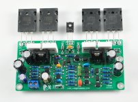
NONE OF THESE BOARDS HAVE ONE OUTPUT PAIR - THE MINIMUM IS 2 PAIRS.
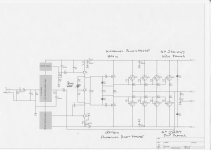
Appeal to LJM_LJM for Schematic L20V9.2
Hello from Tasmania LJM' could you please post the schematic for the L20V9.2 and circle the capacitor that you talk about in the previous note. I just brought a stereo pair kit with the TTC5200/1943 (two pairs per board) It represents terrific value and by all accounts sounds great to the ear.
I have a very smooth DC supply of (+49)-0-(-49)DC which comes from 400VA 0-36VAC + 0-36VAC (extracted from an old Laney bass head) and 2x(40mF+3.3mH LPF) -i.e. one for the positive rail and one for the negative rail.
The preamp installed in the enclosure is a budget priced and once again excellent sounding LC75342 so I have more gain than I need before the input of the L20V9.2
I don't like the idea of removing the DC blocker in that filter, do you have an explanation or comment please?
Cheers, Phil
Last edited:
NONE OF THESE BOARDS HAVE ONE OUTPUT PAIR - THE MINIMUM IS 2 PAIRS.
If you want to use one pair of outputs, all you have to do is lower the voltage, and simply don't install the extra transistors.
If you want to use one pair of outputs, all you have to do is lower the voltage, and simply don't install the extra transistors.
HI there, I think that you missed my point. Earlier in the thread someone became a little heated and stated that one pair of outputs would get hot, but LJM_LJM has never used one pair, two pairs minimum and previously 4 pairs of lower power outputs. This discussion arose (I believe) from Mr. LJM's reluctance to provide schematics and explanations of his circuits. I believe that this is a selfish approach by Mr. LJM because he has been given a gift and doesn't want to share it - or as we have said for years in the Western world and Europe "The bloke is protecting his intellectual property"! Shame on him!!!
I think we should cut Mr. LJM a bit of slack because he is doing in China what we cant do here in Australia or any where else on the planet, - making amps for the poor man. He has made a real go of it and the fact that he and his mates sell more DIY amps than everyone else in the world is a testament to his enthusiasm.
I subscribe to Mr. LJM's philosophy of providing the best quality, hi fidelity and durable products to the poor man. In this way he is somewhat better than other European and Western designers who have assumed a righteous and unquestionable standpoint of authority over their supporters who follow them like sheep - those who have in the past paid an arm and a leg to have a piece of their Guru's electronics on the shelf at home before which all other sheep bow down and pay homage. That kind of thing is not on, as far as I am concerned.
In Bob Dylan's words "The times, they, are, a, Chang, -ing".
Over and out - Jack
Last edited:
LJM_LJM please respond
Ok cobber, I have given you what I reckon is a pretty good rave - so how about a schematic for the L20SE with the two pairs of 5200/1943? Green board on ebay at the moment.
Don't post that crappy blasted thing that got put up before, it is obsolete. Please draw another one showing the schematic for the green board that you mentioned (and I purchased). It should only take a man of your caliber about 10 minutes to draw.
On the bottom of the ebay ad it says "For professionals only?" does the "?" mean that even a professional will be confused? Because I am a professional and I am confused.
A good clear schematic and a few assembly instructions would be nothing more than polite & respectful to your customers.
Sincerely, farmer jack
Hello from Tasmania LJM' could you please post the schematic for the L20V9.2 and circle the capacitor that you talk about in the previous note. I just brought a stereo pair kit with the TTC5200/1943 (two pairs per board) It represents terrific value and by all accounts sounds great to the ear.
I have a very smooth DC supply of (+49)-0-(-49)DC which comes from 400VA 0-36VAC + 0-36VAC (extracted from an old Laney bass head) and 2x(40mF+3.3mH LPF) -i.e. one for the positive rail and one for the negative rail.
The preamp installed in the enclosure is a budget priced and once again excellent sounding LC75342 so I have more gain than I need before the input of the L20V9.2
I don't like the idea of removing the DC blocker in that filter, do you have an explanation or comment please?
Cheers, Phil
After a long time of validation, and a lot of friend's feedback.
The benefits of the input capacitor is obvious, the downside: there is no found.
Don't try to change the power amplifier gain. Because it will lead to distortion.
It is recommended to use higher gain preamp.
Thankyou to Xslav' & ljm, I feel like I am banging my head on wall.
I don't want to change anything. I just want to understand the circuit.
I already like most of it. But have not seen this topology before.
Is it based on a well respected vintage amp?
The fuse-holder would be good on next board?
Xlav' I don't know what pre-voltage is required but the 'hear-say' is very big! Dear Xlav I will copy your suggestion of ??? 6Voltish ??? I have a good little IC based preamp - so there is a pre-gain adjustment on the menu. For me it is just a matter of trial and error. I will report back when I have built my kit. This may take some time as the mail from China takes up to two months to arrive now-days! I must be patient whilst I am very excited about the project.
Thanks to all respondants. Best wishes and bye for now, Jack
About the circuit diagram. I think L20V9. 2 is perfect.
I don't want anyone to change its circuit.
Any change is the result of bad. I am very proud.
I will let it go! I don't want to make bad. Cheers, farmer.
did you read posts 5 & 7?NONE OF THESE BOARDS HAVE ONE OUTPUT PAIR - THE MINIMUM IS 2 PAIRS.
So, have you read the thread and noticed the schematic at #14? That doesn't leave much work for you to do with pencil and paper to fill in just the input stage which will be fairly standard - CCS, LTP, Cascode stage and Current mirror but I suspect it may borrow from L12 which has an unusual feature in the current mirror - that's for you to trace out and ponder over..... I feel like I am banging my head on wall....I don't want to change anything. I just want to understand the circuit.....
Don't forget, L12 was published with errors to throw copyists off the scent too, as you'll read. If you want to respect his IP, don't post your findings here where his competition is just watching and waiting for any free information.
Dont forget to rearrange LPF and HPF for L20 v9,also i used ultra-fast diodes and some old russian capacitors,i guess the only improvements you can make>because the kits transistors are just GREAT not the average MJE -maybe 5541 could b rplaced ^suggestions please
The problem is the preamplifier for it,it has to be Discrete to get a that 350w declared.
so stop posting Toreador ideas and get us some counseling
The problem is the preamplifier for it,it has to be Discrete to get a that 350w declared.
so stop posting Toreador ideas and get us some counseling
I am not at all sure about copyright law and intellectual property rights, but surely if one changes components you have created a different amplifier from the original published schematic.
It then follows that this different version can be discussed openly (with diagrams) without infringing the IP of the designer.
Am I correct?
It then follows that this different version can be discussed openly (with diagrams) without infringing the IP of the designer.
Am I correct?
Unless a valid copyright is identified with a design, it can't simply be claimed but I have no idea of Chinese IP regulation or whether it is applicable to generic audio designs where 'prior art' should nullify any claims of unique design features.
It seems there is a cat-and-mouse game amongst Chinese kitsellers who are surely aware that the only threat to their businesses is themselves. As they are supplying virtually standard designs and copies, already borrowed from earlier commercial, DIY and textbook designs, there's not much to protect unless they simply conceal details that prevent competitors from just copying their work from the web, gratis.
If somone decides to reverse engineer such a board and post the schematic simply because they can, I believe there is little that can be done about it, other than to start over again. OTOH, it might be adding insult to injury subsequently discussing the details here in the OP's thread.
- Home
- Amplifiers
- Solid State
- L20 AMP。use only two NJW0302G