I do work with strain gauging ie extremely small signals and have discovered issues with crimped bnc connectors just for starters.
This is basic stuff for most people here but I thought you guys might like to see how we tackle this stuff.
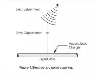
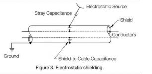
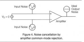
http://www.vishaypg.com/docs/11051/tn501.pdf
Hi 2Pico Dumbs
One document from Vishay lab like rare pearl fished in Pacific ocean don't miss
Very instructive and useful in all diy amplifiers construction this is one i have looking for long time.
Can realy participate to made cleaner signal path.Thanks to 2Pico Dumbs for great contribution


Attachments
when to use twisted pair/ shielded cable
I think this is the appropriate thread for most of my questions.
I need 4 channels of amplification to complete a whole house sound system.
I plan on building 4 F5 amps with two power supplies and two transformers.
Wire questions:
When should I use twisted pair or shielded cables? These are some locations:
1. Main power to transformers.
2. transformers to diode boards
3.F5 boards to speaker terminals.
With shielded cable, I'm aware one only grounds one end of the shield. What is it grounded to? The star point? The PS PCB ground ( for lines to/from the transformer? The F5 PCB ground ( for speaker lines)?
Is 16 gauge stranded wire sufficient for wiring within the amp, exclusive of the PCBs?
The start ground is the same chassis point for both the F5 PCBs and the PSU PCBs?
I would like to put 4 amplifiers and two power supplies in the same chassis.
Perhaps asking if this is feasible belongs on another thread, but I'll ask anyway. The 4U or 5U have a similar foot print, just one is deeper. It appears with the 5U I could stack the PSU filter PCBs and place the two transformers side by side or one their side.
The question then is whether the 300 heat sinks can handle two F5 units per side.
Obviously I'm a novice. I've read thru all the build threads. These are my remaining questions.
Thanks
I have yet to use a lead-free solder that isn't horrible.
TRUE.
And the result can be more noise, because of strange settling behavior.
And above that, these modern lead-free and "real-tree-resin"-free solders will 'poison' the soldering irons: hard black crusts that you get away only with . . old school solder.
Here where it came from for me if you move the cursor over the flag it says New Zealand . RegardsI did notice the ozy kiwi mix up........ While we are similar to each other as aposed to the rest of the world, geographically its like saying Germany and Romania are pretty similar;-)
Hi 2Pico Dumbs
One document from Vishay lab like rare pearl fished in Pacific ocean don't miss
Very instructive and useful in all diy amplifiers construction this is one i have looking for long time.
Can realy participate to made cleaner signal path.Thanks to 2Pico Dumbs for great contribution
Glad someone appreciated that.
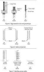
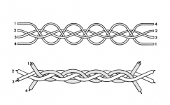
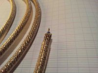
This wiring technique works much better than twisted pair for small signals.
Cable 1 and 2 are paralleled to form one conductor and cable 3 and 4 are paralleled to form the other conductor.
Attachments
This last picture from Vishay document is a try at home i am very motivated.Cable 1 and 2 are paralleled to form one conductor and cable 3 and 4 are paralleled to form the other conductor.
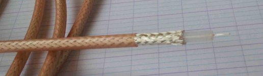
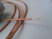
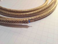
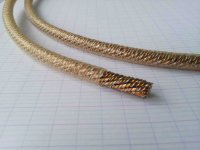
 At the evening i thake pictures of ready made shielded wires first is old Isoda from Japan hybrid metals , next is one candidate i begin collected some quality samples...
What brands of wire You work?
Thanks again 2 Pico Dumbs
Best regards
Attachments
twisted pairs will do for all those connections............I need 4 channels of amplification to complete a whole house sound system.
I plan on building 4 F5 amps with two power supplies and two transformers.
Wire questions:
When should I use twisted pair or shielded cables? These are some locations:
1. Main power to transformers.
2. transformers to diode boards
3.F5 boards to speaker terminals.
With shielded cable, I'm aware one only grounds one end of the shield. What is it grounded to? The star point? The PS PCB ground ( for lines to/from the transformer? The F5 PCB ground ( for speaker lines)?
Is 16 gauge stranded wire sufficient for wiring within the amp, exclusive of the PCBs?
The start ground is the same chassis point for both the F5 PCBs and the PSU PCBs?.............
If you use shielded twisted pairs then the shield is connected to the chassis at both ends.
If you use coax then the shield is the return and the return must be connected to signal ground at both ends.
The shield on the coax I was useing is not totally copper and will be attracted to a magnet. So I don't use it anymore
Magnet don't attracted my shielded wires i can sleep at night.
Thanks Flg for revelated this magnetic specyfication.

Well,I beleieve him more than the ego scientific f$%^&s that won't give him a break.
They're not scientists, not even close, they're pushing their own religion.
They're not scientists, not even close, they're pushing their own religion.
Some do indeed.
And then, some have world class level experience in soldering techniques using both lead free and tin/lead, with a full understanding of soldering such that world class facilities request consultation to solve problems.
I provided detailed explanations in both chemical and metallurgical aspects and issues with regard to simply scraping leads.
jn
Some of those who criticise some of what JC claims are genuine scientists, with the qualifications and published peer-reviewed research to prove it. The truth, or otherwise, of what they say does not of course depend on this; truth is truth whoever says it.2 picoDumbs said:They're not scientists, not even close, they're pushing their own religion.
Those who believe that sales figures are evidence for correctly answering engineering questions are perhaps doomed to spend a lot of their money unnecessarily.
Mediocrity is the bastion of those to whom greatness is to be demeaned from. The purpose of hifi equipment is to entertain and involve the listen to the extent they buy it . Any other standard is fool hardy at best and sadly deluded for the most part. Those with out vision condemn the product of other. This is not test equipment for which the psychological variables do not apply. There are at least two parts to designing Great audio gear . 1. the EE part where you build it so it is stable . 2 the art of voicing it so it sells. Those with vision see that there is two part those with out claim there is only one. Many times audiophile see only 2 and those who claim they are engineers see only 1. Sadly both are missing out on the big picture. Important ideas are often dismissed by so called experts that turn out to be very important. This very long treats remind me of the dismissal of wash hand between patients at he end of the 1800 the experts dismissed the germ theory here to the experts dismiss what maters .
No, it was the practitioners (i.e. those making money from patients) who dismissed the germ theory. It was the scientists who advocated it.
'Voicing' something so it sells is what you do to a mild FX box. I'm sure JC would deny doing that - he aims for fidelity as far as I understand it. It is his methods for achieving that which are sometimes (not always) disputed.
'Voicing' something so it sells is what you do to a mild FX box. I'm sure JC would deny doing that - he aims for fidelity as far as I understand it. It is his methods for achieving that which are sometimes (not always) disputed.
Some of those who criticise some of what JC claims are genuine scientists, with the qualifications and published peer-reviewed research to prove it. The truth, or otherwise, of what they say does not of course depend on this; truth is truth whoever says it.
.
Having a piece of paper that says you're a scientist, doesn't make you a scientist. Being employed as a scientist doesn't make you a scientist either. I work with many of these people who are motivated by ego rather than curiosity.
I don't agree with everything JC says but I am not going to waste my time arguing with him. I'd rather build myself a Zen amp and contemplate different circuit ideas, and then hang out with ZM in the pub.
http://www.youtube.com/watch?v=tzSEd7e6tdc
Last edited:
The practitioners as you call them where surgeons and physicians of the day. My point was the so called self proclaimed experts of the day fought those who where correct and dismissed as not knowing of what they spoke. On the ee front the dismissal out of hand of the anode follower for what in an article by Charles Beogli in the late 50s show how the variable output impedance a plus when driving a Baxsandell tone control circuit . That in fact a negative could in some circuits be a great plus . True vision on Charles part . He was one of 4 great ee I have ever meet. ( He was also V.P of Bendix aviation. )No, it was the practitioners (i.e. those making money from patients) who dismissed the germ theory. It was the scientists who advocated it.
'Voicing' something so it sells is what you do to a mild FX box. I'm sure JC would deny doing that - he aims for fidelity as far as I understand it. It is his methods for achieving that which are sometimes (not always) disputed.
I agree that self-proclaimed experts sometimes get it wrong. People who are right don't need to self-proclaim, as truth will eventually come out. I note that it is often the anti-science brigade who proclaim themselves (or their guru) as being experts, on the basis of their ears or their sales, while the scientists/engineers merely attempt to teach them some basic circuit theory or maths etc.
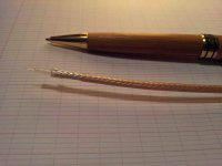
What your wireSo what was that small tan colored coax? is it .100" teflon insulated 28Ga. or???
 for internal amplifier wiring ?
Small 28 dia is must for audio path not little more?
Thanks
Cheers
interesting crossover project with the Neotech solid-core UP-OCC mono-crystal hook-up wire
http://jeffsplace.me/wordpress/?p=4079
Attachments
- Status
- This old topic is closed. If you want to reopen this topic, contact a moderator using the "Report Post" button.
- Home
- Amplifiers
- Pass Labs
- Best solder and wire for Pass diy amplifiers ?