Hi Guys,
I started another thread asking specifically about the oscillation. You can see it here.
http://www.diyaudio.com/forums/solid-state/239204-what-where-can-originating.html
One of the guys suggested disabling the SOA by disconnecting D7 and D8. Once I did that, the oscillation went away. Do you think this points at one of the devices in the SOA or could what ever is causing the DC offset also cause the SOA to oscillate?
Thanks, Terry
What took you so long to implement my suggestion in post #38..You should have resolved the problem in earliest time.
What took you so long to implement my suggestion in post #38..You should have resolved the problem in earliest time.
I did try your suggestion. However, at that point in time, there must have been a solder bridge somewhere because there was no change. It wasn't until later. after a few attempts at cleaning/scratching around all of the traces that I finally got even voltages from side to side. I even replaced all of the transistors on the board. By the time I finally got the voltages straightened out, your suggestion in post #38, which I had tried at that time, was in the distant past. Truth is, the amp worked fine for a short while before the oscillation started up.
It is playing fine now. I finished building the case and installed everything yesterday. It is playing beautifully.
Thanks to all who offered help. I learned a lot on this one. Looking forward to the next build.
Blessings, Terry
Greg, those are protection devices. Vbe should be well below normal conduction range when there is no fault condition.
Thanks Bob, good to know.
Sent from my iPad using Tapatalk HD
Terry,
Glad it's all working now. I know there were a lot of different things you did and many suggestions from members, but do you know what specific change/replacement part you made that fixed it? I know it doesn't matter now, but it's always good to know just what did the trick. I think in one post you mentioned that you had done a wholesale replacement of transistors, but I assume it still wasn't working after that? Thanks for letting us all follow your saga.
Glad it's all working now. I know there were a lot of different things you did and many suggestions from members, but do you know what specific change/replacement part you made that fixed it? I know it doesn't matter now, but it's always good to know just what did the trick. I think in one post you mentioned that you had done a wholesale replacement of transistors, but I assume it still wasn't working after that? Thanks for letting us all follow your saga.
Hi Bob, OK I'll take pics and post them.
Red,
I'll try and run down the saga since I know this ended up being a long thread.
The first issue I had was that neither board would turn on the outputs, so I disconnected them and just dealt with the boards themselves. The first thing I found was that R21 and 22 were the wrong value. It called for 30R and I had 30K in there. I didn't have any 30R so I put 33R in there. That got one of the boards working but not the other. On the bad board I had like 60V on the collector of Q12 when it should be around 44V. At that point I replaced all of the transistors on the board. No change. Then I went through again and re-tinned all of the traces to make sure didn't have any solder breaks or cold joints. Still no change. Then I went around again with a sharp probe and scratched around every trace on the board and finally the voltages came into line. The next thing was to hook up the outputs and see if I got signal and I did so I mounted them on the heatsinks and played some music through them. The board that had originally had problems was fine but the other seemed to distort if it was pushed a little. That is when I hooked up the scope and put a dummy load on it and noticed a strange oscillation. We tried several different things and finally I started a separate thread showing the video I had made showing the oscillation. One of the guys suggested lifting D7 and D8 to disconnect that portion of the circuit. The oscillation disappeared so I tried swapping out Q10 and Q11 once more and that fixed it. Evidently I had done something to damage one of them along the way.
I did try matching Q1-Q4 again on the board I that I had replaced all the devices because I still had about 40mv offset. That didn't really change much. Leach said it should be under 50mv so it's probably fine. I'll take some pics and post them.
I will note that I did something stupid when bolting in the transformer and filter caps. I thought it would be nice and solid if I ran bolts through the transformer and between the filter caps and connect them to a solid aluminum plate and use that as my center-tap for the ground. Fortunately, I brought up the power with a variac and a light bulb. The light started getting brighter at about 2/3 power. I could feel heat coming from somewhere and when I started searching around for it I noticed that the aluminum plate was very hot. That is when I remembered that you cant make a solid loop around the transformer. I cut off the bolt above the transformer and now everything is peaceful. It really is a nice sounding amp. Not really that much stronger than y Low TIM. Maybe just a little stronger bass but over all, they are very close.
Blessings, Terry
Last edited:
Thanks. Interesting about the toroidal tranny. I've always mounted mine horizontal using a single bolt, but I guess a u-bolt ( or equivalent) around it would play havoc with how it functions.Hi Bob, OK I'll take pics and post them.
Red,
I'll try and run down the saga since I know this ended up being a long thread.
The first issue I had was that neither board would turn on the outputs, so I disconnected them and just dealt with the boards themselves. The first thing I found was that R21 and 22 were the wrong value. It called for 30R and I had 30K in there. I didn't have any 30R so I put 33R in there. That got one of the boards working but not the other. On the bad board I had like 60V on the collector of Q12 when it should be around 44V. At that point I replaced all of the transistors on the board. No change. Then I went through again and re-tinned all of the traces to make sure didn't have any solder breaks or cold joints. Still no change. Then I went around again with a sharp probe and scratched around every trace on the board and finally the voltages came into line. The next thing was to hook up the outputs and see if I got signal and I did so I mounted them on the heatsinks and played some music through them. The board that had originally had problems was fine but the other seemed to distort if it was pushed a little. That is when I hooked up the scope and put a dummy load on it and noticed a strange oscillation. We tried several different things and finally I started a separate thread showing the video I had made showing the oscillation. One of the guys suggested lifting D7 and D8 to disconnect that portion of the circuit. The oscillation disappeared so I tried swapping out Q10 and Q11 once more and that fixed it. Evidently I had done something to damage one of them along the way.
I did try matching Q1-Q4 again on the board I that I had replaced all the devices because I still had about 40mv offset. That didn't really change much. Leach said it should be under 50mv so it's probably fine. I'll take some pics and post them.
I will note that I did something stupid when bolting in the transformer and filter caps. I thought it would be nice and solid if I ran bolts through the transformer and between the filter caps and connect them to a solid aluminum plate and use that as my center-tap for the ground. Fortunately, I brought up the power with a variac and a light bulb. The light started getting brighter at about 2/3 power. I could feel heat coming from somewhere and when I started searching around for it I noticed that the aluminum plate was very hot. That is when I remembered that you cant make a solid loop around the transformer. I cut off the bolt above the transformer and now everything is peaceful. It really is a nice sounding amp. Not really that much stronger than y Low TIM. Maybe just a little stronger bass but over all, they are very close.
Blessings, Terry
Live and learn as they say.At their design rails there is only a few dB of difference, so I wouldn't expect to hear much difference unless you were running out of headroom on the lowTIM. I'd think that the cascodes in the output stage might speed it up, so there might be some top end differences.
Do you have a scope, Terry? It might be informative to see whether square waves start rounding off higher on the superamp.
Do you have a scope, Terry? It might be informative to see whether square waves start rounding off higher on the superamp.
At their design rails there is only a few dB of difference, so I wouldn't expect to hear much difference unless you were running out of headroom on the lowTIM. I'd think that the cascodes in the output stage might speed it up, so there might be some top end differences.
Do you have a scope, Terry? It might be informative to see whether square waves start rounding off higher on the superamp.
I do have a scope but not sure what you are looking for. I would be happy to hook it and take some pictures. I could easily do it for both the Low TIM and the Superamp.
As you asked, here are some picks. I'm the only one I know who likes diamond plate so don't be too shocked when you see it.


Lol,
Now that you mention it, my wife had just said that it looks pretty but not for a living room. I told her that it is actually designed to be mounted in a rack. For all but one of the amps I have built I made the face plate rack size. I just haven't put in the mounting holes. If I ever decide to mount them in a rack I will do that then.
Blessings, Terry
Just a hair under 7 spaces. It is 12" tall, 7 spaces is 12.25". Close enough for me.
Here it is in the A/B amp stack in the room. On top is the Low TIM, then the Superamp, then the Symasym and on the bottom my first DIY build, the Eliot P101 three channel.

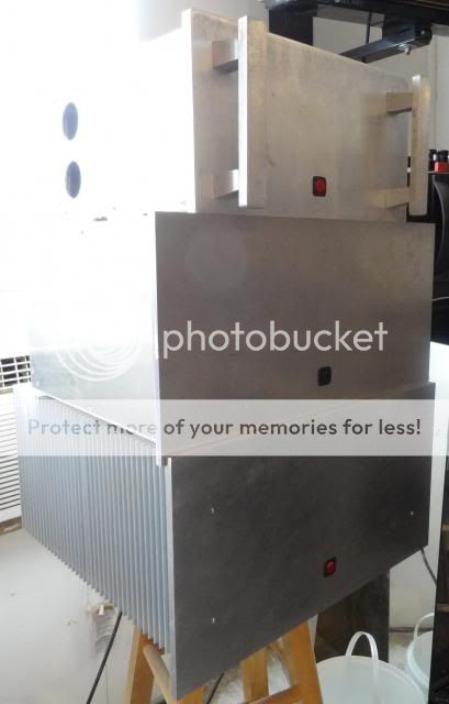
Here is a pic of the room heaters. Top is a TO3 based Krell KSA50, middle is a KSA50 with 6 pair of Plastic outputs per side. On the bottom is my Aleph-X. Soon to be something else since it sounds lousy. I may turn it into a KSA100 that I have boards for.
Here it is in the A/B amp stack in the room. On top is the Low TIM, then the Superamp, then the Symasym and on the bottom my first DIY build, the Eliot P101 three channel.

Here is a pic of the room heaters. Top is a TO3 based Krell KSA50, middle is a KSA50 with 6 pair of Plastic outputs per side. On the bottom is my Aleph-X. Soon to be something else since it sounds lousy. I may turn it into a KSA100 that I have boards for.

- Status
- This old topic is closed. If you want to reopen this topic, contact a moderator using the "Report Post" button.
- Home
- Amplifiers
- Solid State
- Leach Superamp, round 2