leach superamp
Hi Terry, some amplifiers have slight voltage differences between them due to parts used such as the resistors being high or low in there values and this can have and effect on volt reading's.. if possible try one amp module by it'self and take readings.
One thing to do is earth the large heat-sinks as they can act like antennas thus picking up stray fields and the amplifier under test can start to oscillate as it pick's this up and amplifies it.. use shielded leads for the i/p put cables and keep o/p leads away from psu's...
regards A.
I don't have anything other than what is called for in the BOM and schematic. What's weird is I can't find anything different between the two boards yet one works perfectly and one oscillates. The one that oscillates has stopped oscillating a couple of times. There are some slight voltage differences between the two as noted in post #192.
I'm not opposed to adding some things if they will work.
Thanks
Hi Terry, some amplifiers have slight voltage differences between them due to parts used such as the resistors being high or low in there values and this can have and effect on volt reading's.. if possible try one amp module by it'self and take readings.
One thing to do is earth the large heat-sinks as they can act like antennas thus picking up stray fields and the amplifier under test can start to oscillate as it pick's this up and amplifies it.. use shielded leads for the i/p put cables and keep o/p leads away from psu's...
regards A.
Hi Anthony,
I grounded the sinks and moved the PS as far as I could without making new wires. (About a foot away) I have had a shielded cable on the input from the beginning.
Without a load on it, the output looks good. There has to be some reason that the oscillation is only on the lower part of the sound wave. The other channel looks the same with a load as without.
Thanks.
PS. I bought the "The Audiophile's Project Sourcebook" Good reading so far.
There's plenty to read within that book,from in stages to o/p's plus protection circuits plus all the terms used vas..long tail dif input,pole comp caps even power amp circuits to build.
I've build a few of mosfet designs all with good very good performance for them selves..
ps check out the chapter on ways of biasing the o/p stage via voltage drops across the emitters.
Regards A.
I've build a few of mosfet designs all with good very good performance for them selves..
ps check out the chapter on ways of biasing the o/p stage via voltage drops across the emitters.
Regards A.
Yes, I'm looking forward to reading through it. I'm sure I will learn a lot.
The bias thing has been a little weird on the Leach. All of the emitter resistors read different. They are not far off from each other but they are off.
If nothing else, I am learning. This may end up being a mono amp for my sub.
The bias thing has been a little weird on the Leach. All of the emitter resistors read different. They are not far off from each other but they are off.
If nothing else, I am learning. This may end up being a mono amp for my sub.
The bias thing has been a little weird on the Leach. All of the emitter resistors read different.
Watch for fake transistors!!! Inconsistent bias readings between parallel units is a big RED FLAG. That could explain why one channel is oscillating and the other not. Got a close-up of the markings on the outputs? And where did you get them?
I got the O/P's from On-semi as samples back when they still did that. Everything else came from Mouser. Here's a shot of them in the channel. I can take a better one of the devices is you need but like I said, they came directly from ON.
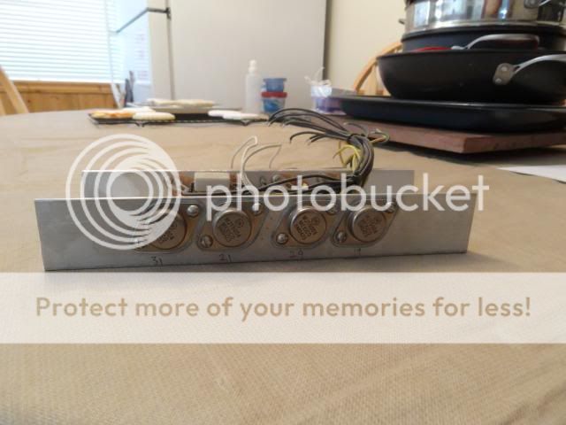
I also just replaced all of them on the bad channel and got the exact same readings so I don't think it is the O/P's.

I also just replaced all of them on the bad channel and got the exact same readings so I don't think it is the O/P's.
leach superamp
One way to set bias up is to check readings over emitter resisters and let the amplifier warm up and re-trim where need and aim for equal measurements.
Mine are .33R per the BOM.
I see from 15mv to 19mv across them when set to 125ma at F1.
One way to set bias up is to check readings over emitter resisters and let the amplifier warm up and re-trim where need and aim for equal measurements.
Vre with a single pair will show a difference top to bottom due to tolerance of resistor values (Re).
Vre with multiple pairs will show a difference top to bottom and between adjacent due to resistor tolerance ands due to transistor tolerance.
Matching of resistors is very easy. That should never be ignored.
Matching of Transistors is much more difficult, but good Vre agreement can be achieved with careful Amateur Methods of Matching, especially of Vbe @ bias current.
Hi Guys,
I started another thread asking specifically about the oscillation. You can see it here.
http://www.diyaudio.com/forums/solid-state/239204-what-where-can-originating.html
One of the guys suggested disabling the SOA by disconnecting D7 and D8. Once I did that, the oscillation went away. Do you think this points at one of the devices in the SOA or could what ever is causing the DC offset also cause the SOA to oscillate?
Thanks, Terry
You could just have a bad SOA limit transistor, or it might be in backwards. Don't just assume TO-92's are ok without checking. I was the victim of FAKE MPSA06's - or maybe just mismarked - the d*mn things were PNP.
If the SOA is partially on all the time or otherwise malfunctioning it could be the cause of DC offset. It will pull the VAS way out of balance.
If the SOA is partially on all the time or otherwise malfunctioning it could be the cause of DC offset. It will pull the VAS way out of balance.
leach superamp
Amplifier short circuit protection is designed to trigger when amp's experiences a load lower than 2 ohms or a short circuit to it's o/p thus limiting it's current to the out put stage to a safe point and hopefully if the circuit is designed well enough it's devices will survive.. such circuits are called vI limiters...
most amplifier circuits also incorporate catch diode's to clam emf to the supply rails.. the leach amp as these added across it's o/p to each supply rails to the o/p. Using mpsa42/92 for the short circuit protection.
Hi Guys,
I started another thread asking specifically about the oscillation. You can see it here.
http://www.diyaudio.com/forums/solid-state/239204-what-where-can-originating.html
One of the guys suggested disabling the SOA by disconnecting D7 and D8. Once I did that, the oscillation went away. Do you think this points at one of the devices in the SOA or could what ever is causing the DC offset also cause the SOA to oscillate?
Thanks, Terry
Amplifier short circuit protection is designed to trigger when amp's experiences a load lower than 2 ohms or a short circuit to it's o/p thus limiting it's current to the out put stage to a safe point and hopefully if the circuit is designed well enough it's devices will survive.. such circuits are called vI limiters...
most amplifier circuits also incorporate catch diode's to clam emf to the supply rails.. the leach amp as these added across it's o/p to each supply rails to the o/p. Using mpsa42/92 for the short circuit protection.
Hi Anthony,
I replaced Q10 & Q11 again today and it cured the oscillation. I had recently replaced them so didn't look there. I must have hurt them somewhere along the way. The only issue I have now is that there is still a 40mv offset. Q18 and Q20 both measure about 70mv on the emitters while all the others are around 30mv. How do I trace that back?
Thanks, Terry
I gave up tweaking offset on my A75s when I got under 60 mV. Nelson Pass himself said anything under 100 mV is fine.
Since Professor Leach didn't design offset adjustability into the circuit, it comes down to input pair matching. If you want to match, make a jig with a socket that simulates operating conditions. I'd use +/- 15V (since I have that handy) and make a CCS to feed the DUT and load it with 1K. Ground the base. Measure the voltage across the 1K to match (mV=mA through 1K) You could even make a differential tester. Match NPN devices to each other, and PNP devices to each other. If you have a large enough test batch, you might be able to match NPN pair to PNP pair, which will give the lowest offset.
Since Professor Leach didn't design offset adjustability into the circuit, it comes down to input pair matching. If you want to match, make a jig with a socket that simulates operating conditions. I'd use +/- 15V (since I have that handy) and make a CCS to feed the DUT and load it with 1K. Ground the base. Measure the voltage across the 1K to match (mV=mA through 1K) You could even make a differential tester. Match NPN devices to each other, and PNP devices to each other. If you have a large enough test batch, you might be able to match NPN pair to PNP pair, which will give the lowest offset.
Hi Terry, Q14 feeds Q16 and this part feed's to both 18 and 20 check the volts there also do volts compare with good channel and that point. sometimes its just down to tolerances within components.
If possible carry out a full 1k signal test and see how the amp holds up.
Regards A.
If possible carry out a full 1k signal test and see how the amp holds up.
Regards A.
Hi Guys,
I used this circuit to match the inputs.
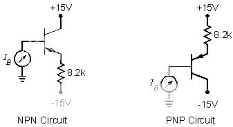
I had 25 of each and while the PNP's were easy to match against themselves they were too far off from the NPN's to match that way so Q1 matches Q2 and Q3 matches Q4. Still the offset. Guess I'll just live with it. It sounds very nice.
Now to build a case and set up the power supply.
Thanks!
Hi Andrew,
Yes, this is what he said;
I was only able to accomplish the third choice. However, I only have 40mv on the one channel and 1.0mv on the other.
As promised, I have filled out a schematic with what should be the necessary voltages to be able to trouble shoot the boards. Hopefully others will be able to find this should they have need.
Blessings, Terry

Yes, this is what he said;
For minimum dc offset at the output, Q1 through Q4 should preferably have matched current gains. The current gains can be measured with a curve tracer or with a multimeter which has this capability. Ideally, all four transistors should be matched. If this cannot be achieved, the second choice is for Q1 and Q3 to be matched and Q2 and Q4 to to be matched. The third choice is for Q1 and Q2 to be matched and Q3 and Q4 to be matched. The typical dc offset at the amplifier output is less than 50 mV.
I was only able to accomplish the third choice. However, I only have 40mv on the one channel and 1.0mv on the other.
As promised, I have filled out a schematic with what should be the necessary voltages to be able to trouble shoot the boards. Hopefully others will be able to find this should they have need.
Blessings, Terry

Last edited:
- Status
- This old topic is closed. If you want to reopen this topic, contact a moderator using the "Report Post" button.
- Home
- Amplifiers
- Solid State
- Leach Superamp, round 2