Hi Richard,
These are some good points. Asymmetrical music waveforms, particularly in the low-frequency region, can cause differences in rail currents that can affect lots of things, at least in some amplifier designs. These effects can show up both in the supply itself (unbalanced secondary DC currents in some rectifier circuits) and in output stages, which often have PSRR that is quite a bit less than we would like. Asymmetrical rail sag can cause problems. Whether these deviations propogate back to the input and driver circuits is also an issue. Of course, we want those circuits to have very high PSRR for a lot of good reasons.
It is far too easy for us to sometimes overlook that the rails are dirty and moving.
Cheers,
Bob
Going further backward, the audio can be seen on the ac power line.... the power amp's current draw and Z of the ac line/source. And, what affect on distortion THD+N does that have on down stream equipment operating on the same ac line is a variable to performance and good sound. Wouldnt show up when individually testing componets but as a system test it contributes to the total distortion we actually have to listen to.
Thx-RNMarsh
Last edited:
but you can do the Thevenin/Norton interchange on them - giving the "infinite" Vsource in series with a "infinite" R such that V/R = I as a model of the ideal Isource
likewise "infinite" Isource in parallel with the "infinitesimal" R such that IR = V is a model of the ideal Vsource
The keyword here is 'model' versus the definition
")
jan
The power amp but one with the ODNF, the hawksford error correction one has too high THD, I had a look at the sims.
No worry Damir, Ill be patient, maybe Ill breadboard the input stage for now as Im also thinking of a new headphone amp.

Manso, I don't think that HEC distorts much more than ODNF amp. ODNF has lower THD1k(0.000211%) compared with HEC(0.000720%) but quite similar at 20kHz, 0.004248% ODNF and 0.004743% for HEC and all that at 4Vpp at the output.
I will proceed at this thread http://www.diyaudio.com/forums/solid-state/238252-odnf-no-gnfb-power-amp-6.html#post3550195 with more simulations not to steal this thread.
Going further backward, the audio can be seen on the ac power line.... the power amp's current draw and Z of the ac line/source. And, what affect on distortion THD+N does that have on down stream equipment operating on the same ac line is a variable to performance and good sound. Wouldnt show up when individually testing componets but as a system test it contributes to the total distortion we actually have to listen to.
Thx-RNMarsh
What about the reservoir caps. They have to replenish the charge taken. Would this not have a smoothing effect on the mains?
Mind you I have seen lights dim with some big work horses. Carver comes to mind.
What about the reservoir caps. They have to replenish the charge taken. Would this not have a smoothing effect on the mains?
Mind you I have seen lights dim with some big work horses. Carver comes to mind.
In an ordinary linear power supply the charging of the reservoir capacitors on each half-cycle occurs with very narrow pulses, whose area must equal the average current draw from the DC side of the supply. The amplitude of these impulses can be quite remarkable, easily in the tens of amps. Thus rather wideband interference can be created and thrown back into the mains. Making the reservoir capacitors larger does not mitigate this problem.
Cheers,
Bob
@RM: Keeping in mind the charging as mentioned by Bob, meaning that the power supply transformer is effectively disconnected from the load maybe 80% or more of the time, while dumping charge in the caps the other 20% or less, I have a hard time to imagine a mechanism that causes audio to appear on the mains line.
jan
jan
Now pick a pencil and do some algebra. Either way you calculate (TCS * TIS or VAS1 * VAS2), the end to end voltage gain is gm*Rl*Beta where gm is the input stage transconductance (actually, 2*gm for a current mirror loaded input stage), Rl is the output stage input impedance and Beta is the VAS2 current gain (can be Beta1*Beta2 if a beta enhancer/emitter follower is used). As you see, the VAS2 emitter degeneration doesn't come into the equations.
Please apply this line of reasoning to a CMOS op-amp, the Aol is not infinite.
The audio does not 'appear' on the mains, but if the power supply's functioning to supply the energy needed to reproduce the audio at higher levels means that current spikes with a wide spectrum spread appear on the mains then problems of SQ can arise.@RM: Keeping in mind the charging as mentioned by Bob, meaning that the power supply transformer is effectively disconnected from the load maybe 80% or more of the time, while dumping charge in the caps the other 20% or less, I have a hard time to imagine a mechanism that causes audio to appear on the mains line.
jan
This is the advantage of connecting equipment to different mains spurs - using distance to attenuate the interference to some degree.
@RM: Keeping in mind the charging as mentioned by Bob, meaning that the power supply transformer is effectively disconnected from the load maybe 80% or more of the time, while dumping charge in the caps the other 20% or less, I have a hard time to imagine a mechanism that causes audio to appear on the mains line.
jan
You are making this waaay too difficult. Doesnt anyone measure these kinds of things anymore?
-RM
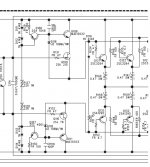
[post #4107]Bob your thoughts on this outputstage plz. In essence the driver stage, its not a straightforward cascode. Japanese highend like Accuphase use it on top models.
That's an interesting looking arrangement that would allow the use of low-Vce BJT devices in positions Q109 and Q110. One would expect that with the relaxation of Vce and SOA requirements of these transistors, you could pick fast devices with high beta. What's unclear to me is whether Q108 and Q111 need to be fast devices in order for this approach to give an overall speed improvement.
In this specific case, I was surprised to find that Q109 and Q110 were high-Vds devices. Perhaps the cascode arrangement is simply to prevent Cgd modulation? I am confused as to why Q109 and Q110 have been drawn as JFETs - when I googled those part numbers I found MOSFETs.
Also, not sure what the purpose of D119 is? Is it simply to allow the dynamic impedance between Q109 and Q110 sources to be lowered without increasing said transistor's quiescent current?
Last edited:
Please apply this line of reasoning to a CMOS op-amp, the Aol is not infinite.
Are we talking about cmos op amps here? I though it's about the standard Thompson bipolar topology.
Cmos amplifiers are of course a completely different kettle of fish. The open loop gain is defined by the channel (drive and load) geometries, as both the stage transconductance and the load are depending on these. Also, the concept of degeneration doesn't make sense, at least in the way it is used in bipolar gain stages.
Textbook stuff, for mosfets and jfets, at least two things, lambda and Cgd.
Cgd is the gate drain capacitance. It's nonlinear and is responsible for a good chunk of the mosfet or jfet large signal distortions. When the power supply voltage goes up, Cgd goes down as the inverse square of the power supply voltage. If you consider the variation of dCgd/dV vs. V, it's approximatively a negative slope straight line, which means that the Cgd variations with the input voltage (Vcc-Vi) are lower, hence lower distortions. Due to the square law variation of Cgd, distortions are of even harmonics.
Lambda is the channel modulation parameter. To consider the channel modulation effects, the mosfet/jfet drain current has to be corrected by a (here, simplified) factor of (1+Lambda*Vds). Lambda is responsible for the finite output impedance of the mosfet/jfet devices; the output impedance is r0=(1/Lambda + Vds)/Id. As you see, the output impedance is a function of Vds and Id. A large signal analysis of the mosfet/jfet gain stage immediately reveals that the channel modulation effect leads to harmonic distortions. Although the physics and the expressions are different, the external circuit effects of finite Lambda are similar with the Early voltage in bipolars.
Solution? Cascoding, before anything else. By keeping the Vgd constant, the Vgd Miller capacitance is kept constant, while the cascoding device Cgd (or C0b for bipolars) is no longer Miller, but shunt to the stage output. By using a large Early voltage bipolar as cascading device, the lambda effect can also be largely cancelled. It's the same philosophy as cascoding in bipolar stages, to build a better equivalent device (here, with lower Cgd effect and higher output impedance) out of two devices.
Yes, this is all in the text books. I want to demonstarte that harmonics can be reduced thru cancelling techniques... cascoding reduces the C (J.Miller) affect but does not cancel it.... as in a null. Some things can be done to reduce the C (Miller et al) without cascoding and without extra expense. Or even before/after as an adjunct to cascoding.
To take it a little further.... I use these oldies but goodies to measure the C of capacitance of semiconductors: It is similar (if not exactly the same equip) used to get the data curves, such as those shown below:


As you can all see, the C drops towards a plateau as the Vds increases and this directly helps with lowering the distortion from those C's. In the example the 2H and 3H drop by 10dB going from 12v to 18v.
.JPG")

However, when the C's are matched the cancelation can be almost total. In fact the 100X more expensive analyzer shows it into its' noise floor.

Such neutralization techniques are more common as the VDC supplies are below 5v and two devices limit the output ability to get things done with just cascoding. Often with HF amps even using cascoding, the neutralization methods are still needed and help with stability.
So, I showed that with matching C in/Cout(Miller) by padding up the input C can cancel distortion and that adjusting the Vds can be used to match C's and cancel distortion. Here are two more commonly used techniques used but with Diff amps:
Note, if the back biased diodes are made from the same transistor model/part as the diff amp is, the C will track very closely and offer a null over a wider operating range.

Thx-RNMarsh
Last edited:
Yes, this is all in the text books. I want to demonstarte that harmonics can be reduced thru cancelling techniques... cascoding reduces the C (J.Miller) affect but does not cancel it.... as in a null. Some things can be done to reduce the C (Miller et al) without cascoding and without extra expense. Or even before/after as an adjunct to cascoding.
To take it a little further.... I use these oldies but goodies to measure the C of capacitance of semiconductors: It is similar (if not exactly the same equip) used to get the data curves, such as those shown below:
View attachment 361471
View attachment 361472 View attachment 361473
As you can all see, the C drops towards a plateau as the Vds increases and this directly helps with lowering the distortion from those C's. In the example the 2H and 3H drop by 10dB going from 12v to 18v.
View attachment 361479 View attachment 361480
However, when the C's are matched the cancelation can be almost total. In fact the 100X more expensive analyzer shows it into its' noise floor.
View attachment 361485
Such neutralization techniques are more common as the VDC supplies are below 5v and two devices limit the output ability to get things done with just cascoding. Often with HF amps even using cascoding, the neutralization methods are still needed and help with stability.
So, I showed that with matching C in/Cout(Miller) by padding up the input C can cancel distortion and that adjusting the Vds can be used to match C's and cancel distortion. Here are two more commonly used techniques used but with Diff amps:
Note, if the back biased diodes are made from the same transistor model/part as the diff amp is, the C will track very closely and offer a null over a wider operating range.
View attachment 361487
Thx-RNMarsh
I sure do love that old equipment! Micro-micro amperes! Wow, sounds like picoamps.
Cheers,
Bob
Yes, this is all in the text books. I want to demonstarte that harmonics can be reduced thru cancelling techniques... cascoding reduces the C (J.Miller) affect but does not cancel it.... as in a null. Some things can be done to reduce the C (Miller et al) without cascoding and without extra expense. Or even before/after as an adjunct to cascoding.
To take it a little further.... I use these oldies but goodies to measure the C of capacitance of semiconductors: It is similar (if not exactly the same equip) used to get the data curves, such as those shown below:
View attachment 361471
View attachment 361472 View attachment 361473
As you can all see, the C drops towards a plateau as the Vds increases and this directly helps with lowering the distortion from those C's. In the example the 2H and 3H drop by 10dB going from 12v to 18v.
View attachment 361479 View attachment 361480
However, when the C's are matched the cancelation can be almost total. In fact the 100X more expensive analyzer shows it into its' noise floor.
View attachment 361485
Such neutralization techniques are more common as the VDC supplies are below 5v and two devices limit the output ability to get things done with just cascoding. Often with HF amps even using cascoding, the neutralization methods are still needed and help with stability.
So, I showed that with matching C in/Cout(Miller) by padding up the input C can cancel distortion and that adjusting the Vds can be used to match C's and cancel distortion. Here are two more commonly used techniques used but with Diff amps:
Note, if the back biased diodes are made from the same transistor model/part as the diff amp is, the C will track very closely and offer a null over a wider operating range.
View attachment 361487
Thx-RNMarsh
We have a PAR410 in one of our labs, never used it. I suppose it's designed to measure C-V curves at 1MHz, right?
What you say sounds similar to the neutrodyne principle, used in the 1920's radio receivers and eventually in Tektronix oscilloscopes (to improve/extend the Y output stage frequency response). While I am sure it can be used to tune down the even harmonics, I think reproducibility would be it's critical downsize. Why don't you use current mirrors and be done with it?
I think the best possible performance of cancelling even distortions, based on device matching, is achieved in ICs like the OPA1632. Differential mode distortions are down to -130dB (due to distortion cancellation), while the single ended/common mode performances are, of course, much worse. You can't even hope to reach such performances in a discrete circuit.
That's an interesting looking arrangement that would allow the use of low-Vce BJT devices in positions Q109 and Q110. One would expect that with the relaxation of Vce and SOA requirements of these transistors, you could pick fast devices with high beta. What's unclear to me is whether Q108 and Q111 need to be fast devices in order for this approach to give an overall speed improvement.
In this specific case, I was surprised to find that Q109 and Q110 were high-Vds devices. Perhaps the cascode arrangement is simply to prevent Cgd modulation? I am confused as to why Q109 and Q110 have been drawn as JFETs - when I googled those part numbers I found MOSFETs.
Also, not sure what the purpose of D119 is? Is it simply to allow the dynamic impedance between Q109 and Q110 sources to be lowered without increasing said transistor's quiescent current?
Harry, in some of the amps use of BJTs are made for the driver as well as the cascode, this model only happenened to use mosfets. Indeed the cascode arrangement in driver stage can have many advantages, SOA, high speed devices can be used ect. Im not sure for the purpose of that diode either. To me most strange is the cascode connection, note the connection from D116 and D118 to the mosfets sources instead of being just connected to each other which is the more common cascode arrangement. You might think this connection is of no consequence but spice will show you otherwise. To me resembles hawksford but here we are dealing with a common collector arrangement. I have difficulty getting stability from sims with this arrangement but it does work and is used in very expensive amps so the designers Im sure know what they are doing. Ive build the stage exactly as in that schematic some years back as a quick experiment and found it indeed superior to Selfs EF2 and it even outperformed a triple outputstage although by not much. Not shown in that schematic is the peculiar compensation scheme required around the driver to get it stable. Note with the more common cascode arrangement no such compensation is necessary. From measurering the commercial versions of amps using this circuit one notices improved 20Khz distortion figures. They also dont display the sudden and rapid increase in distortion one usually finds when a class AB amp gets close to clipping. Distortion here climbs more gradually. These advantages are the selling points in the brochures of these amps. Note this arrangement has been used since about 1982 by Accuphase.
I find it strange that simulation displays the arrangement as being unstable no matter what devices are used but the real actual circuit works as intended.
I think the best possible performance of cancelling even distortions, based on device matching, is achieved in ICs like the OPA1632. Differential mode distortions are down to -130dB (due to distortion cancellation), while the single ended/common mode performances are, of course, much worse. You can't even hope to reach such performances in a discrete circuit.
I bring these things up as either alternatives or as adjunct to getting the lowest distortion possible with 1. discrete parts and 2. for power amps in particular. Not what can be done or is being done for the commercial market and IC manufacturing. Seperate devices are hard to find that are exactly compilemtary for the DIY'er.
The null can be sharp or broad... it can be handled in the design. Of course, broad is better for mass production. In looking at the HP-339A osc circuitry, they use a jFET that has to have a cancelation/phase shifting C changed in value when ever they had to start with a new batch of jFETs. So be it to get the lowest harmonic distortion possible.
The cascode stage was first introduced with tubes which have a much better quality interlectode capacitance so the BW extention being found thru C (Miller) reduction is not a big gainer in reducing harmonics.
Secondary benefits using cascode with semiconductors is some reduction in harmonics and increase in PSRejction. But that is secondary. CCS are better to address PSR et al.
There is a place for cancellation topologies to the existing amplifer design bag of tricks -- esp with descrete power amps. It can be a simplifying method and it can be a final tune for absolute lowest distortion when combined with other popular methods. Let's try some ideas.
THX-RNMarsh
Last edited:
..... sure has been quiet .....
A few more ideas for topologies to cancel the non-linear capacitance that causes so much distotion; though used for increasing speed and BW increase but you can use it for the non-linear C distortion cancelling for lowest Harmonic distortion:

And Scott Wurcer's idea (AES 1992 #3231) for opamp distortion cancelling via Cn.

There are many cancelling techniques found via web search.
Thx-RNMarsh
A few more ideas for topologies to cancel the non-linear capacitance that causes so much distotion; though used for increasing speed and BW increase but you can use it for the non-linear C distortion cancelling for lowest Harmonic distortion:
And Scott Wurcer's idea (AES 1992 #3231) for opamp distortion cancelling via Cn.
There are many cancelling techniques found via web search.
Thx-RNMarsh
Last edited:
- Home
- Amplifiers
- Solid State
- Bob Cordell's Power amplifier book