Well, that took a bit to find ... amazing how sometimes something you think will be easy to get hold of again just plays hard to get ...: http://www.diyaudio.com/forums/soli...lls-power-amplifier-book-119.html#post2413197
Thanks a lot for finding it. Sorry to be a pain, but please could you provide a post #? That link doesn't work for me due to my forum settings. Thanks again.
Ohhh ... the pain of it all! ...
#1184, or w3.diyaudio.com/forums/solid-state/171159-bob-cordells-power-amplifier-book-119.html#post2413197
Hope that gets you there ...
#1184, or w3.diyaudio.com/forums/solid-state/171159-bob-cordells-power-amplifier-book-119.html#post2413197
Hope that gets you there ...
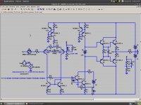
OK. That circuit has no supply rejection for the current sources (i.e. R4 and R10 should be split into two equal sized resistors, with caps connected at the midpoint and returned to the rail.) and no supply rejection for the negative rail supply of the front end (e.g. RC filtering or preferably something with a cap-multiplier for the negative-rail supply to the VAS/TIS and input stage). Presumably if you add these THD is much less affected by rail variations?
Also, one would expect performance to increase if Q8/Q9 are replaced with KSC2690A/KSA1220A and Q10/Q11 are replaced with MJL3281A/MJL1302A.
Also, one would expect performance to increase if Q8/Q9 are replaced with KSC2690A/KSA1220A and Q10/Q11 are replaced with MJL3281A/MJL1302A.
Yes, if you give the neg. rail of the front end a perfect supply then THD at 20kHz barely varies when the supplies elsewhere have more realistic impedances.
To me, the implication is that the part of the circuitry solely concerned with amplication needs to have effectively excellent PSRR over the full range of frequencies that it has to deal with. Whether that is done in a way that is considered part of the circuit, or as part of the power supply, is really nothing more than a POV, a way of mentally separating the components within an assembly
To me, the implication is that the part of the circuitry solely concerned with amplication needs to have effectively excellent PSRR over the full range of frequencies that it has to deal with. Whether that is done in a way that is considered part of the circuit, or as part of the power supply, is really nothing more than a POV, a way of mentally separating the components within an assembly
[Check your SIM models C and be sure they are accurate and not the same value used for both N and P type.]
OK. Here comes the rub for Power Amplifiers and something I am working towards --> As you picked up on... the PS variation makes a huge difference if it changes;
With power amps, the follower type output stage isnt regulated and whether MOSFET or BJT, asymetrical waveforms coupled with high power draw will load down one P.Supply line more than the other and it can be enough voltage drop delta to increase distortion.
And, change THD even more than loading both lines to drop equally, as would be the case with sine wave testing. Its a theory to see what happens in real live circuits.
I would like to see some work on this get SIM'ed, bench tested and published.
Thx-RNMarsh
Hi Richard,
These are some good points. Asymmetrical music waveforms, particularly in the low-frequency region, can cause differences in rail currents that can affect lots of things, at least in some amplifier designs. These effects can show up both in the supply itself (unbalanced secondary DC currents in some rectifier circuits) and in output stages, which often have PSRR that is quite a bit less than we would like. Asymmetrical rail sag can cause problems. Whether these deviations propogate back to the input and driver circuits is also an issue. Of course, we want those circuits to have very high PSRR for a lot of good reasons.
It is far too easy for us to sometimes overlook that the rails are dirty and moving.
It might be interesting to monitor the dynamic asymmetry of the rails by summing them together with a resistor network and then looking at the result on a scope to see just how much asymmetrical rail sag there is under demanding program material.
Another useful test might be to run a THD test in the presence of a very large-amplitude low-frequency sinusoid, like 10Hz. This has some similarities to the SMPTE IM test of 60 & 6000 at 4:1, but is potentially more stressful, and is looking for THD distortion product variations rather than AM on a 7kHz carrier.
These are, of course, lab tests. Much of this can probably be simulated as you suggest.
One technique that can be useful is to employ an entirely separate bridge rectifier and reservoir capacitor (smaller) to create the rail voltages for the input, VAS and driver circuits. Even if not regulated, these rails will be much less prone to rail sag, symmetrical or not, under periodic heavy loading.
Cheers,
Bob
Don't forget that reservoir caps have wide tolerances and this can make sag asymmetric regardless of music asymmetry.
On post number links... I have discovered that changing
to
Makes it work again. Why the forum software is not capable of this is beyond me.
On post number links... I have discovered that changing
to
Makes it work again. Why the forum software is not capable of this is beyond me.
Don't forget that reservoir caps have wide tolerances and this can make sag asymmetric regardless of music asymmetry.
On post number links... I have discovered that changing
[http://www.diyaudio.com/forums/solid-state/171159-bob-cordells-power-amplifier-book-82.html#post3563202]
to
[http://www.diyaudio.com/forums/solid-state/171159-bob-cordells-power-amplifier-book.html#post3563202]
Makes it work again. Why the forum software is not capable of this is beyond me.
Thanks a lot! Everyone take note. I will submit a bug report in the appropriate place.
PSRR is involved for the gain stages. But using only a pair of jFETs in compl. follower configuration.... similar to most any output stage in a power amp.... using very well regulated supplies (HP6237B) and changing their B+/B- levels give different THD. For example, running the supply at a fixed 24v or a fixed 12v level causes the THD to go from .0025% to .016% THD. This is with constant fixed levels.... dont know yet about a ramping or changing rate of supply voltage affect.
What is it in the devices themselves -- not the whole amplifier circuitry -- that cause the THD to change and what can be done about it in this follower stage area, only? Their On resistance change and is modulated? Better complimentary devices needed? Or is it ....... ?
THx-RNMarsh
What is it in the devices themselves -- not the whole amplifier circuitry -- that cause the THD to change and what can be done about it in this follower stage area, only? Their On resistance change and is modulated? Better complimentary devices needed? Or is it ....... ?
THx-RNMarsh
Last edited:
What is it in the devices themselves -- not the whole amplifier circuitry -- that cause the THD to change
Textbook stuff, for mosfets and jfets, at least two things, lambda and Cgd.
Cgd is the gate drain capacitance. It's nonlinear and is responsible for a good chunk of the mosfet or jfet large signal distortions. When the power supply voltage goes up, Cgd goes down as the inverse square of the power supply voltage. If you consider the variation of dCgd/dV vs. V, it's approximatively a negative slope straight line, which means that the Cgd variations with the input voltage (Vcc-Vi) are lower, hence lower distortions. Due to the square law variation of Cgd, distortions are of even harmonics.
Lambda is the channel modulation parameter. To consider the channel modulation effects, the mosfet/jfet drain current has to be corrected by a (here, simplified) factor of (1+Lambda*Vds). Lambda is responsible for the finite output impedance of the mosfet/jfet devices; the output impedance is r0=(1/Lambda + Vds)/Id. As you see, the output impedance is a function of Vds and Id. A large signal analysis of the mosfet/jfet gain stage immediately reveals that the channel modulation effect leads to harmonic distortions. Although the physics and the expressions are different, the external circuit effects of finite Lambda are similar with the Early voltage in bipolars.
Solution? Cascoding, before anything else. By keeping the Vgd constant, the Vgd Miller capacitance is kept constant, while the cascoding device Cgd (or C0b for bipolars) is no longer Miller, but shunt to the stage output. By using a large Early voltage bipolar as cascading device, the lambda effect can also be largely cancelled. It's the same philosophy as cascoding in bipolar stages, to build a better equivalent device (here, with lower Cgd effect and higher output impedance) out of two devices.
Last edited:
Hi Waly,
Good answer!
That is what I also believe it to be..... in fact that is what I said in the beginning... the device C's are important and can be used to cancel distortion. In the output stage the C goes down as the supply voltage went up. And they do not track each other [as compliments] well as the PS voltage goes down. besides cascoding, at a given PS voltage, we should be able to add a small amount of C to one device that matches the other and get a null in 2H (H2). Cascoding is better if there are large variations to deal with or back biased diodes that track the active devices c changes can be used. That is for the low cost version over cascoding with expensive power devices.
[When I added R4, I changed the c value of that device to match the compliment].
Thx-RNMarsh
Last edited:
Textbook stuff, for mosfets and jfets, at least two things, lambda and Cgd.
Cgd is the gate drain capacitance. It's nonlinear and is responsible for a good chunk of the mosfet or jfet large signal distortions. When the power supply voltage goes up, Cgd goes down as the inverse square of the power supply voltage. If you consider the variation of dCgd/dV vs. V, it's approximatively a negative slope straight line, which means that the Cgd variations with the input voltage (Vcc-Vi) are lower, hence lower distortions. Due to the square law variation of Cgd, distortions are of even harmonics.
Lambda is the channel modulation parameter. To consider the channel modulation effects, the mosfet/jfet drain current has to be corrected by a (here, simplified) factor of (1+Lambda*Vds). Lambda is responsible for the finite output impedance of the mosfet/jfet devices; the output impedance is r0=(1/Lambda + Vds)/Id. As you see, the output impedance is a function of Vds and Id. A large signal analysis of the mosfet/jfet gain stage immediately reveals that the channel modulation effect leads to harmonic distortions. Although the physics and the expressions are different, the external circuit effects of finite Lambda are similar with the Early voltage in bipolars.
Solution? Cascoding, before anything else. By keeping the Vgd constant, the Vgd Miller capacitance is kept constant, while the cascoding device Cgd (or C0b for bipolars) is no longer Miller, but shunt to the stage output. By using a large Early voltage bipolar as cascading device, the lambda effect can also be largely cancelled. It's the same philosophy as cascoding in bipolar stages, to build a better equivalent device (here, with lower Cgd effect and higher output impedance) out of two devices.
Well put, Waly.
Cheers,
Bob
Hi Waly,
Good answer!
That is what I also believe it to be..... in fact that is what I said in the beginning... the device C's are important and can be used to cancel distortion. In the output stage the C goes down as the supply voltage went up. And they do not track each other [as compliments] well as the PS voltage goes down. besides cascoding, at a given PS voltage, we should be able to add a small amount of C to one device that matches the other and get a null in 2H (H2). Cascoding is better if there are large variations to deal with or back biased diodes that track the active devices c changes can be used. That is for the low cost version over cascoding with expensive power devices.
[When I added R4, I changed the c value of that device to match the compliment].
Thx-RNMarsh
Hi Richard,
Bear in mind that Cgd is less of a problem in source follower MOSFET output stages that are driven with a fairly low impedance, as from a BJT EF driver. This is why, even though the MOSFET DC input impedance is very high, I consider MOSFET amplifiers where the MOSFETs are driven directly from the VAS to be sub-optimal.
Cheers,
Bob
Hi Bob. Nice forum over here. As you know, I have been looking at the 2nd and 3rd order things which are needed when you try to get well below -120dB THB levels. Under the banner of distortion cancellation is what I was thinking about.
Tuning the C by varying R4 was just to raise awareness of the supply voltage relationship with distortion. When the C's of the device change, so does the distortion unless something is done about it. Its another view of things which might add to someone's design for lower distortion.
Your point about low drive source Z is also an important point, of course. And, easily measurable/demonstated means to minimize the C affects I am talking about.
Are there some more ways? How many more ways are there... especially, some very simple and cheap to do ways.
Thx-RNMarsh
Last edited:
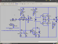
kgrlee, here is my simulation. I did the same thing with an opposite-polarity frontend, and I don't see any strange harmonic cancellation. I do see that the EF reduces THD by ~34db, which is less than the OLG increase of 40db. Notice how few things changed between the schematics.
However, reversing the Hfe mismatch of Cordell's output models I'm able to reduce THD by almost half - most of the reduction in the 2nd harmonic. Just like the extra 5db reduction in THD you see in your plots. Without the enhancer, the effect isn't so large - no because it increases linearity but because the H2 cancellation goes out of tune.
However, reversing the Hfe mismatch of Cordell's output models I'm able to reduce THD by almost half - most of the reduction in the 2nd harmonic. Just like the extra 5db reduction in THD you see in your plots. Without the enhancer, the effect isn't so large - no because it increases linearity but because the H2 cancellation goes out of tune.
Attachments

kgrlee, here is my simulation. I did the same thing with an opposite-polarity frontend, and I don't see any strange harmonic cancellation. I do see that the EF reduces THD by ~34db, which is less than the OLG increase of 40db. Notice how few things changed between the schematics.
However, reversing the Hfe mismatch of Cordell's output models I'm able to reduce THD by almost half - most of the reduction in the 2nd harmonic. Just like the extra 5db reduction in THD you see in your plots. Without the enhancer, the effect isn't so large - no because it increases linearity but because the H2 cancellation goes out of tune.
This has turned out to be a very very interesting discussion. I must admit that I have in the past paid little attention to cancelations or distortion mitigations like these. What do I mean by this? My thrust has usually been focused on minimizing the effects of nonlinearity in each device or sub-circuit. Often, in discrete circuits, I have taken it as a given that mismatches would be there, and that we needed to deal with them by minimizing their effects, as opposed to manipulating their effects. I hope I am explaining this effectively.
For example, I have never sought to work the nonlinearities of the VAS against those of its current source load in a single-ended VAS arrangement - I have just tried to minimize the nonlinearity of each. Similarly, where Ccb distortion was at hand, I did not actively try to make the badness of it in one transistor work AGAINST the badness of it in another. I knew that such cancellations would often exist functionally, but just regard such cancellation as gravy, rather than to try to manipulate it to advantage. I must admit that, philosophically, I don't like to depend on any matching of undesired effects; but maybe I am not giving the possible benefits enough credit.
The mismatch in output stage PNP and NPN transistors is another example. Using the best output transistors with minimal beta droop, and output stages like Triples that reduce dependence on output transistor beta, and even selecting NPN/PNP pairs is an obvious direction that I have always pursued. However, taking those differences as a given and then trying to have their ill effects fight each other is something I have not pushed. An example of this is the Bryston output stage, where NPN and PNP output devices are used in both the top and bottom parts of the output stage.
I must point out that I am not referring to distortion cancellations that result from relatively dependable errors that tend to track and match. Perhaps the best example of this is the simple differential pair, where we automatically depend on its cancellation of even-order errors, and where we try to maximally exploit that cancellation by using a current mirror load to force the two transistors in a pair to operate at the same quiescent current. Likewise, I am also not referring the the predictable distortion cancellation that occurs in a cascomp input stage.
Anyway, bottom line is that this is an area where I may have underestimated the possible benefits, especially in certain amplifier architectures and circuits.
Cheers,
Bob
Hi Bob. Nice forum over here. As you know, I have been looking at the 2nd and 3rd order things which are needed when you try to get well below -120dB THB levels. Under the banner of distortion cancellation is what I was thinking about.
Tuning the C by varying R4 was just to raise awareness of the supply voltage relationship with distortion. When the C's of the device change, so does the distortion unless something is done about it. Its another view of things which might add to someone's design for lower distortion.
Your point about low drive source Z is also an important point, of course. And, easily measurable/demonstated means to minimize the C affects I am talking about.
Are there some more ways? How many more ways are there... especially, some very simple and cheap to do ways.
Thx-RNMarsh
In other words -- what caught my eye was the small debate here about reducing THD via more linearization vs cancellation and dont they mean the same thing.
Cascoding minimizes the distortion, it doesnt cancel it. Negative fb minimizes the THD. But, cancel means to me -- null to zero or into the noise floor. Before I drop it altogether here.... is there a method to null/cancel THD to zero over a broad range of volts and freqs? I have only seen a couple concepts about this approach so far.
Another way instead of stage by stage approach: Maybe this will wet someone's appitite in the cancellation approach and have this lead to something else -->

Thx-RNMarsh
Last edited:
Most of the types of cancellation available to us in a power amp only correct the 2nd or 3rd harmonic - leaving the higher order harmonics as they are. Feedback on the other hand can reduce all harmonics - although this is not necessarily so simple.
I have a very interesting question. We know that greater open-loop linearity improves harmonic spectrum, lowering high-order harmonics. But what if that internal linearity is improved only by reducing the lowest-order harmonics, like in kgrlee's case?
I have a very interesting question. We know that greater open-loop linearity improves harmonic spectrum, lowering high-order harmonics. But what if that internal linearity is improved only by reducing the lowest-order harmonics, like in kgrlee's case?
I am focused on 2H and 3H as everything beyond those are a lot lower. They can be dealt with later after 2H and 3H are gone.
Thats IMO and what I am doing A.T.T. No doubt further reduction in THD will use a combination of linearizing and cancellations techniques.
-RM
Thats IMO and what I am doing A.T.T. No doubt further reduction in THD will use a combination of linearizing and cancellations techniques.
-RM
Last edited:
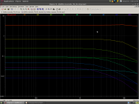
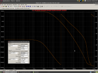
Okay, continuing the exercise of investigating how the circuit mentioned earlier is sensitive to power supply 'imperfections', tried increasing the pure resistive component of the rails, with an ideal voltage source now used for the negative rail of the front end.
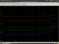
Next to "fall" is the positive rail of the front end, at 300 mR the THD went through the roof, the output started entering clipping ...
So, now have an ideal voltage feeding the positive side of the front end - 'correct' behaviour again restored ...
Next to "fall" is the positive rail of the front end, at 300 mR the THD went through the roof, the output started entering clipping ...
So, now have an ideal voltage feeding the positive side of the front end - 'correct' behaviour again restored ...
I am focused on 2H and 3H as everything beyond those are a lot lower. They can be dealt with later after 2H and 3H are gone.
Thats IMO and what I am doing A.T.T. No doubt further reduction in THD will use a combination of linearizing and cancellations techniques.
-RM
Hi Richard,
Here's where there may be some controversy - and why some dismiss THD as being relevant to sound quality. Whether true or not, many agree and argue that it is the high order nonlinearities that impair sound quality. At the same time, it is usually "easier" to reduce 2nd and 3rd, be it with feedback or cancellation methods.
The result can be that an amplifier measures better with THD when we smoosh the easy ones because they dominated the THD number in the first place.
The cancellation methods are great, but I think we all agree that they largely are effective only for the lower-order products. These are what I would call the "softer" distortions. Early effect nonlinearity is an example of a mechanism that causes softer distortion, at least in my mind.
A good example of the more difficult and problematic distortions is output stage crossover distortion. It can cause a spray of high-order harmonics and IM products.
Anyway, I'm trying not to takes sides here, but to just point out why a single-number THD is limited in its usefulness. A THD result where the content of the first 7 or so harmonics is reported is probably more useful.
At the same time, I'll readily admit that a low number for 20kHz THD is a worthy goal among others, since it will allow less "wiggle room" for other nonlinearities to likely be problematic. A tube amp with 0.1% THD is quite good (because that 0.1% is probably of low order), while a SS amp with 0.1% THD COULD be awful (but not necessarily). We don't know what high-order stuff is being masked by the 0.1%. A SS amp with 0.001% THD20 is less likely to be having a lot of really bad high-order stuff because 0.001% can't mask as much bad stuff.
You can see I'm struggling to make this point.
Here is another example from my own experience. I was once working on a MOSFET amplifier design which I thought to be pretty good. It measured something like 0.02% THD20. Not bad, many might say. However, I was disappointed because I "knew" that it really should have been better than even that. So I didn't stop there. I scratched my head a lot. I ultimately discovered that the amplifier was breaking into a brief 50MHz parasitic oscillation burst on the trailing peak of a large-signal sinewave. Having finally learned of the problem, I was able to kill it. Distortion dropped to about 0.005%. In this case, the "true", "legitimate" distortion of the amplifier was being masked by the distortion created by the parasitic oscillation burst.
Cheers,
Bob
- Home
- Amplifiers
- Solid State
- Bob Cordell's Power amplifier book