Thanks, LC! Finally received the great masterpieces! Still pending for power supply and casing!!! ")
James
An externally hosted image should be here but it was not working when we last tested it.
James
Hi LC,
At least you know your schematic. We who don't know your schematic has to disassemble and measure smd caps ....
Changes from published schematics (v 1.4) that I discovered so far:
Input filter frequency changed.
Added shunt compensation to VAS
Removed gate resistors
Added voltage drop resistor to CCS's
Bias pot now rheostat connected instead of potentiometer connected.
There is probably more that I missed.
One simple question LC, will you release schematic or not?
Last edited:
I don't know about you guys but I actually use VSSA modules to make some amplifiers.
Hi LC,
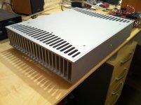
Where did you buy that nice chassis?
Thanks
Do
Hi LC,
Where did you buy that nice chassis?
I think a couple of those nicely handmade boxes will cost him a few amp modules
Why would you do that as I already published BOM in this thread in which all the parts are specified.We who don't know your schematic has to disassemble and measure smd caps ...
Installation manual will keep you on track to finalize the VSSA module to working conditions. Sch is published in post #300, some values were changed in a favour to greater quality that you cannot find in other similar threads and normally any author has the right to make modifications or changes to improve the quality.

Last edited:
Hi LC,
Where did you buy that nice chassis?
Thanks
Do
Would you like to have one like this?
Why would you do that as I already published BOM in this thread in which all the parts are specified.
Installation manual will keep you on track to finalize the VSSA module to working conditions. Sch is published in post #300, some values were changed in a favour to greater quality that you cannot find in other similar threads and normally any author has the right to make modifications or changes to improve the quality.
Hi LC,
You have added/changed quite a few parts so a new schematic is certainly necessary.
If you don't release a new schematic, I will. I just don't want to do unnecessary work if you plan to release the schematic anyway.
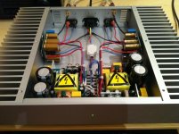
does it get hot inside ?
Inside volume has natural air flow from bottom plate perforation to exhaust in upper back plate.
Inside air is moderately heated primarily by SMPS, no heatsinks (VAS or drivers etc) or other heat generators inside.
..... no heatsinks (VAS or drivers etc) or other heat generators inside.
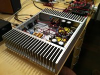
sure is ... the whole back of the heatsink, or two actually ...they get hot too, don't they ?
That would not be a good idea since among initial GB this is also a potential OEM module for future release, no Copyright for that you own.If you don't release a new schematic, I will. I just don't want to do unnecessary work if you plan to release the schematic anyway.
sure is ... the whole back of the heatsink, or two actually ...they get hot too, don't they ?
Hot?
Warm yes, but hot c'mon Don't you think VSSA turned out to be nice OEM module for different kind of implementations. I got quite a few requests from different manufacturers for that kind of future activity. Are you not satisfied with opportunity to taste VSSA? It is working perfectly if you just follow Installation manual. As this thread revealed no DIY-er here was pleased with even SMD soldering so why on earth would somebody disassemble them and make modifications, no rational reason for that. You can trust me for once, module has optimized values and it works perfectly like it is.Hi LC,
It seems the truth creeps out.
I'll certainly check my rights prior to publishing.

Is there something important in the GB participants only to send secret schematic beyond housekeeping that can make a whole lot of difference to a self made previously published VSSA aside the physical board design advantages? If there is crucial differentiation not published to a GB we have to move it to vendors area as it is considered a non disclosed real product offering then.
Hi Salas
Schematic is the same as published in post #300.
I'm just sayin that is really hard to improve something and to stay in the same size or parts count, so why bother was meant in this way. Still someone can do own PCB or experiment.
If no schematic (even in the manual) then the whole thread goes to Vendors area.
Salas please specify crucial differentiation.If there is crucial differentiation not published to a GB we have to move it to vendors area as it is considered a non disclosed real product offering then.
Salas please specify crucial differentiation.
We don't vet circuits as mods, its in the rules. GB area is open source, else its Vendors area. Its the forum's steady policy. I had asked again (as quoted) early enough before the send out and warned for there must be a fully corresponding schematic.
We don't vet circuits as mods, its in the rules. GB area is open source, else its Vendors area. Its the forum's steady policy. I had asked again (as quoted) early enough before the send out and warned for there must be a fully corresponding schematic.
OK, agreed with that explanation. Thanks Salas.
- Home
- Vendor's Bazaar
- VSSA Lateral MosFet Amplifier