I have some questions.
I've been toying with high slewrate designs in the simulator. I've been trying to get Lfets to stop ringing with smaller base stoppers. According to simulation, the J162 gets a lot of Gm droop at 5A or so and becomes very vulnerable to instability. Is this accurate to real life?
Furthermore, it seems in high-slewrate designs EF drivers are a potentially huge mistake. If the amp bursts into oscillation, the drivers go into class B mode and act like a rectifier jacking up bias to only a few hundred simulated amps. Even if current limited to 7A or so, in a prototype this would be a huge issue, mandating a diamond driver stage. A diamond stage will collapse bias instead, and still retains indefinite transient drive ability if you use a cap to connect the emitters. A useful amp should never be in danger of oscillation, but this is not something I would want to deal with in a prototype. I could not find a way to keep a normal EF driver from throttling the bias.
I've been wanting to make a prototype and I'm in the initial layout stage. I have a dual PCB covered in masking tape. I will solder the components over the top so that each side of the PCB can act as a ground plane. I want to use one side of the PCB this way for the power ground plane right up against the LFETs, and the other side of the PCB for frontend ground plane. My question is, since the ground planes are right next to each other, will they interact? I will of course route the signal ground on its own wire above the ground plane.
Each PAIR is a separate loop. There is no loop where both pairs are involved to "filling more space with stray loops".
No, there is no DC loop through the twisted pairs. There is however a loop through the trafo capacitance which may resonate.
Even if there is no common loop, twisting wires does eradicate the field. Just because we twist them doesn't let us put them just anywhere. They still have to be out of the way, and if you have to keep them separated, you need to find space for two radiators instead of one. And if the fields of each pair cancel, why do they need to be separated from each other?
The best explanation I've seen for the advantage of dual bridge is in post #38 here.
That makes sense. It seems if you use a single rectifier you're limited to connecting your reservoirs to the first star ground, and then tapping amp ground from that so that voltage gradients don't cause noise. But with dual rectifiers, as long as you keep secondary returns separate and closer to their respective reservoirs than amp ground, it should be much less critical. This "remote" configuration will allow more flexibility in placement of reservoirs.
totem pole drivers
Hi Keane,
Agreed.
Cheers,
E.
[..]
Furthermore, it seems in high-slewrate designs EF drivers are a potentially huge mistake. If the amp bursts into oscillation, the drivers go into class B mode and act like a rectifier jacking up bias to only a few hundred simulated amps. Even if current limited to 7A or so, in a prototype this would be a huge issue,
Hi Keane,
Agreed.
Admittedly, it's more safe, but we don't want that either, as the OP stage gets under-biased under such conditions.mandating a diamond driver stage. A diamond stage will collapse bias instead,
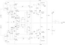
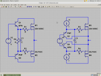
By using a simple cap? I have my doubts. IMHO, using separate totem pole drivers for top and bottom O/P trannies is more apt. See for an example fig. 12 in Super TIS , Q39..Q42.and still retains indefinite transient drive ability if you use a cap to connect the emitters.
Cheers,
E.
Last edited:
@ Bob Cordell
Always a good idea, which i've done for years. Plus putting a 3rd higher voltage cap directly across + & - rails @ the PCB supply input, or @ the OT's.
With regard to the 2 Caps, these high current "dirty" common returns should NOT be on the PCB, but instead taken seperately to the star point. I mention L/M/H current returns in here, with a screenie.
http://www.diyaudio.com/forums/solid-state/236554-grounding-earthing-connections.html
Re - having substantial filter caps right on the board close to the output transistors.
Always a good idea, which i've done for years. Plus putting a 3rd higher voltage cap directly across + & - rails @ the PCB supply input, or @ the OT's.
With regard to the 2 Caps, these high current "dirty" common returns should NOT be on the PCB, but instead taken seperately to the star point. I mention L/M/H current returns in here, with a screenie.
http://www.diyaudio.com/forums/solid-state/236554-grounding-earthing-connections.html
By using a simple cap? I have my doubts. IMHO, using separate totem pole drivers for top and bottom O/P trannies is more apt. See for an example fig. 12 in Super TIS , Q39..Q42.
Cheers,
E.
Hi Edmund. I actually did think of using a full EF for each gate after posting that, but I didn't want to add 2 more transistors. However the effectiveness of this idea seems to really justify it.
WRT the diamond and cap, if the cap is large enough I don't see how it should be different from an EF driver, except in recovery effects. In simulation the diamond configuration behaved better. However my implementation of it probably is very significant, and possibly suboptimal. Still more to explore.
I have some questions.
I've been toying with high slewrate designs in the simulator. I've been trying to get Lfets to stop ringing with smaller base stoppers. According to simulation, the J162 gets a lot of Gm droop at 5A or so and becomes very vulnerable to instability. Is this accurate to real life?
Furthermore, it seems in high-slewrate designs EF drivers are a potentially huge mistake. If the amp bursts into oscillation, the drivers go into class B mode and act like a rectifier jacking up bias to only a few hundred simulated amps. Even if current limited to 7A or so, in a prototype this would be a huge issue, mandating a diamond driver stage. A diamond stage will collapse bias instead, and still retains indefinite transient drive ability if you use a cap to connect the emitters. A useful amp should never be in danger of oscillation, but this is not something I would want to deal with in a prototype. I could not find a way to keep a normal EF driver from throttling the bias.
I've been wanting to make a prototype and I'm in the initial layout stage. I have a dual PCB covered in masking tape. I will solder the components over the top so that each side of the PCB can act as a ground plane. I want to use one side of the PCB this way for the power ground plane right up against the LFETs, and the other side of the PCB for frontend ground plane. My question is, since the ground planes are right next to each other, will they interact? I will of course route the signal ground on its own wire above the ground plane.
I must confess I have not seen this one yet - i.e., EFs rectifying and boosting the bias current when an output stage goes into oscillation. A very interesting observation to say the least.
The glib answer is that a MOSFET output stage should never be allowed to go into a parasitic oscillation. In my MOSFET power amplifier with error correction article of long ago, I pointed out the danger of MOSFETs in parasitic oscillation and described some ways to eliminate it.
Parasitic oscillation endangers the MOSFET itself, since the gate oxide can be breached by only about 20V. In oscillation, the internal parasitic oscillation voltage can be greater than that at the pins, so back-back 15V zeners across the gate-source may not protect the device.
MOSFETs, especially vertical, are fast devices, and inductances and gate electrode capacitances can easily work together to form a Colpitts or Hartley oscillator topology. That's why I recommend Zobel gate snubbers to kill the Q of any oscillator topology. Often something on the order of 100 ohms and 100pF will do. This is what you have to do if you want to operate with smaller resistances in series with the gate.
Cheers,
Bob
By using a simple cap? I have my doubts. IMHO, using separate totem pole drivers for top and bottom O/P trannies is more apt.
I agree. The charging/discharging currents for the N and P types are not typically equal because the input capacitance vs Gm is not equal. There is nothing can be done about that, it is the differences in physical material used to make the N-ch and P-ch devices.
Although this circuit uses planer stripe FETs which is a version of vertical devices, this is how I am driving the gates using two seperate totem pole drivers in my home brew vertical mosfet amp for Hi-Fi. (left out are the small base/collector stopper resistors for the HF transitors) Seems to work very well.
Note: typically the pair is chosen based on Gm, the devices chosen here do not have similar Gm. I only did this on purpose to create a 'worse case scenerio' for the error correction.

Attachments
Replace the gate stoppers with ferrite beads - works on mosfets and bipolars.
I had a low power output EF oscillating at 20 MHz - ferrite bead stopped it. Works on cascodes as well.
On my bip output stages, my class A driver stage halves are connected through a 12-15 Ohm resistor, so a very low impedance. this helps prevent the bootstrapping issue to mention - I dont use a speed-up cap either. Ive replaced the 4.7 Ohm base stoppers with ferrite beads and can confirm that the triple remains stable (200 MHz scope) and cannot be provolded into oscillation.
Ferrite beads. Awesome.
Last edited:
EKV MOSFET models?
Bob, this MOSFET discussion gives me an excuse to ask if you've unearthed your EKV MOSFET models.
I'm trying to replicate some Jurassic designs of mine using dis new fangled 21st century LTspice stuff. It seems to be unnervingly 'accurate' with my simple BJT amps. I'm now trying some MOSFET inventions of mine.
Response & stability stuff seems close to 'real life' but I don't believe the THD residuals.
Re-reading your book, I notice you say EKV models are required to do a good job for THD. Duu.uuh!
Would the Toshiba 2sk1530/2sj201 and IR IRFP240/9240 be still your output devices of choice?
I must confess I have not seen this one yet - i.e., EFs rectifying and boosting the bias current when an output stage goes into oscillation. A very interesting observation to say the least.
I think the danger arises from having a very low capacitance TIS output node (a few tens of pF). In this case the drive ability of the TIS and it's max risetime are great whereas in most designs, the VAS is the first stage to slew limit.
I still don't know why a diamond would have less transient drive ability, disregarding recovery effects, if C2 is large enough to have negligible impedance. I would expect it to be more behaved because there is a very small G-S loop. For vertical outputs, C2 should be larger.
I'm also very interested in the EKV models. Andy_C and others were supposed to have created some, but I could never get them to work.
And whatever came of this?
http://www.diyaudio.com/forums/soli...ells-power-amplifier-book-47.html#post2790907
Attachments
Replace the gate stoppers with ferrite beads - works on mosfets and bipolars.
I had a low power output EF oscillating at 20 MHz - ferrite bead stopped it. Works on cascodes as well.
On my bip output stages, my class A driver stage halves are connected through a 12-15 Ohm resistor, so a very low impedance. this helps prevent the bootstrapping issue to mention - I dont use a speed-up cap either. Ive replaced the 4.7 Ohm base stoppers with ferrite beads and can confirm that the triple remains stable (200 MHz scope) and cannot be provolded into oscillation.
Ferrite beads. Awesome.
Ferrite beads are very useful and very inexpensive. Some audiophile designers do not like them, however. This is one of those things that, if they really do hurt the sound quality, it seems to be unmeasurable. This is not unlike the concern often expresed in the high end about using resistors that do not have fully copper leads.
Cheers,
Bob
Back to the driven cascode, where we discussed the reduction in distortion that can happen when the cascode bases are driven with a version of the common mode signal that appears at the tail of the LTP.
Recall that there were two issues discussed (at least). The first was Self's assertion that the effect of the distortion from a non-driven cascode could not be seen in SPICE simulations.
The second was how to derive the signal to drive the cascode bases. One was to take it directly from the tail of the LTP, level-shifting it by a DC amount suitable for driving the cascode bases. In this approach, sometimes the tail voltage is buffered before being level-shifted and applied to the cascode.
The other approach, described in my book, is to create a replica of the feedback signal with another feedback network and use that signal to drive the cascode bases. This signal is essentially equal to the inverting signal applied to the LTP, but in the feedback amplifier this is essentially the same as the common mode signal at the tail up to fairly high frequencies. This approach has the advantage of not messing with the sensitive LTP tail node.
The other day I was investigating a simple input stage for another project, and revisited the driven cascode matter. The input stage included an LSK389 JFET cascoded and then loaded with a current mirror. All very conventional. I simulated the amplifier less the output stage. The whole thing was a very conventional amp architecture with a single-ended VAS run at 10mA and a driver circuit run at 15mA. The output was buffered by a unity VCVS before being applied to the feedback network, so no distortion would result from any loading of the driver.
Here are the results at 1kHz and at 20kHz for the IPS-VAS with and without driving the cascode with the replica signal. These results are at an output signal level of 20V rms, representing 50 watts into 8 ohms.
At 1kHz, distortion went from 0.000042% down to 0.000013% when driven, a 3.2:1 reduction.
At 20kHz, distortion went down from 0.0008% down to 0.00008% when driven, a 10:1 reduction.
Cheers,
Bob
Hi Bob, what is the distortion if you use the LTP emitters instead ?
A complete output stage has phase shift and I have to wonder whether your results have anything to do with using a VCVS, that is if these results are better than the LTP tail ones. Could you show us the topology ??
I think the danger arises from having a very low capacitance TIS output node (a few tens of pF). In this case the drive ability of the TIS and it's max risetime are great whereas in most designs, the VAS is the first stage to slew limit.
I still don't know why a diamond would have less transient drive ability, disregarding recovery effects, if C2 is large enough to have negligible impedance. I would expect it to be more behaved because there is a very small G-S loop. For vertical outputs, C2 should be larger.
I'm also very interested in the EKV models. Andy_C and others were supposed to have created some, but I could never get them to work.
And whatever came of this?
http://www.diyaudio.com/forums/soli...ells-power-amplifier-book-47.html#post2790907
I don't like diamond buffer output stages for anything but low power e.g headphone amps or small signal buffers. If you are driving a power amplifier output stage, the drive to the individual output devices is not symmetrical - in itself not the end of the world, but what happens if the load dips to 2 or 3 ohms and your output device hFE gain is say 50 (quite typical). To be alto cater for this you need a very hefty current source load on the diamond follower stage emitters.
A straight class A Locanthi driver stage is preferable in my view.
A straight class A Locanthi driver stage is preferable in my view.
True.

Bob,
Yes, some high end designers don't like them. The trick is to use them and not tell anybody you have done it.
That's a great idea! Either that or refer to them as miniature Bybee devices
.Cheers,
Bob
Bonsai,
Do you use the surface-mount ferrite beads that you solder in series with the circuit, through-hole ones that consist of a wire surrounded by a cylindrical ferrite core, or just bare cores that you pass a conductor (such as a PCB trace, component leg, resistor) through?
Do you find that you are given sufficient information from manufacturers regarding saturation current and/or impedance vs. frequency? Have you experimented with many different types?
Hi Bob, what is the distortion if you use the LTP emitters instead ?
A complete output stage has phase shift and I have to wonder whether your results have anything to do with using a VCVS, that is if these results are better than the LTP tail ones. Could you show us the topology ??
Hi Manso,
I did not try using the LTP emitters to drive the cascode bases. I was mainly trying to see how big the reduction would be in driven vs non-driven cascode (and of course to verify that a very big reduction would occur using the replica drive technique that I prefer). I was very happy with the results, but can't honestly say whether it would have been much different one way or the other when using the LTP tail (either directly or buffered) to drive the cascode bases.
The closed-loop response of the amplifier will have pretty small phase shift in the audio band. If an amplifier has a ULGF of 1MHz, the closed-loop phase shift will be ideally about 45 degrees at 1MHz and much less at lower frequencies. Of course, in a real, non-ideal amplifier the closed-loop phase at ULGF will tend to be a bit more, but that is of little consequence.
I used the VCVS to drive the feedback path(s) so as not to load the output of the IPS-VAS, as I wanted to see and isolate the fundamental distortion capability of that circuit.
Cheers,
Bob
I don't like diamond buffer output stages for anything but low power e.g headphone amps or small signal buffers. If you are driving a power amplifier output stage, the drive to the individual output devices is not symmetrical - in itself not the end of the world, but what happens if the load dips to 2 or 3 ohms and your output device hFE gain is say 50 (quite typical). To be alto cater for this you need a very hefty current source load on the diamond follower stage emitters.
A straight class A Locanthi driver stage is preferable in my view.
I would never use a Diamond for a BJT output stage, except perhaps for the first driver pair in a triple. However I've been referring to an Lfet output stage, not a BJT output stage.
If you take a diamond and EF driver pair in an FET output stage and bias them at the same current, it will take the same level of loading to send each into class B. So I don't consider a Diamond stage "weak" when used with FET output stages and a large enough gate bridge cap. The gate currents may be asymmetrical, but this shouldn't matter at audio where the drivers should never enter class B.
Furthermore, If the drivers do enter class B, the diamond's tendency to collapse bias is no different from the EF's tendency to boost it, except that the former is not a risk.
- Home
- Amplifiers
- Solid State
- Bob Cordell's Power amplifier book