hahfran said:So I am quite suspicious about enthusiastic reports about DIY current dumping amps if it is nowhere mentioned how the inductivity is physically realized.
Hello,
I have tested recently efficiency of error correction at different variants of the coil in the bridge and by the circuit and method proposed in the Vanderkooy&Lipshitz paper.
I have tested common low diameter (~2-3mm) inductor. Coil made on 20 mm diameter by a single wire. And Coil made on 20mm diameter by twisted two wires.
Pictures of crossover spikes you may see on this page. (In Russian)
Prictures 2, 3, 4 different coils and 5,6,7 (different values of capacity in the bridge).
Pictures 2 was done at 80 Ohm load and rest at 22 ohm. Hence first has less spike, but at 22 Ohm load the error is huge, especially in shape of the residual signal. It is rather not a smooth sine.
In all pictures the amplitude of residual sine was about 20 mV.
The sharp spike on last pictures may be compensated well by adjust of the bridge resistor (47 Ohm).
An considerable improvement of the error gives adding of a bias into output stage.
Output of test is following. Most effective compensation gives multi-wire coil with large diameter. I suppose that the reason of it is a Q-factor of the coil and bridge as whole.
PS I want to test this result also in my clone of the quad 909.
I get quite similar results however I scope output -x*input.
The crossover spikes are of course frequency dependent in amplitude.
Using Hevreng's analysis which is appended to Vanderkooy Lipschitz
I think I have to cope with the physical reality : design a plane spiraled inductor ( Fermat spiral looks good for that purpose) on PCB which is calculated to have the property of a particular inductance , measure it with resonant frequency method ( including the deviation induced by series resistance ) and then re- calculate the bridge parts including rb. A good enough approximation could be a MLSSA signal instead of a frequency variable sine and counter. I have a couple of well specified precision capacitors.
If that works out I could make my 8- transistor current dumping 6 -fold
without any more individual adjusting. It should have the property of being insensitive to a definite range of supply voltage variations except a few resistors in the class A so one design from 20 watts to 200 watts.
If not then I'll make the Quad303 redesign which has a pretty good musical sound.
Air core inductors are quite consistent from one to another provided you wind in the same manner with the same gauge wire. Any and all lead wires to and from the inductor form a leakage inductance that must be taken into consideration.
Depending on circuit layout, the leakage inductance may reach 300 nH, or close to 10% of the value of the part. My present versions of the current dumping amplifier locate the bridge components very close together and minimize the leads on the inductor.
I've had consistent results with the powdered iron cores. The permiability is very low compared to ferrite and molyperm cores and the differences from part to part are minimal. The trick is to select a core that gives 3 uH with a integer number of turns, and that doesn't saturate.
jonusgrumby said:Air core inductors are quite consistent from one to another provided you wind in the same manne
Yes that is the problem....my problem. I am an algebraist. As mathematician I can get everything wrong that has never any practical consequences. As a DIY every false move has practical consequences.
I will now develop a function to compute the inductance, resistance and capacitance of a flat Fermat spiral and then program a plot of it
expose develop and etch a 70 um copper layer coated teflon PCB and then ...well I' ll see.
Thank you anyway.
Originally posted by tvicol
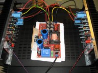
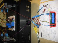
....This is a slightly moded coldamp SMPS which a highly recommend.....
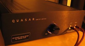
Congratulations with your great Quasar design!
")
You have used the Coldamp SMPS80 to supply the Quasar. I am curious what you have modded on the Coldamp SMPS, and why. Are the mods specifically related to use it as a power supply for the Quasar?
Hans Baas said:
Congratulations with your great Quasar design!
You have used the Coldamp SMPS80 to supply the Quasar. I am curious what you have modded on the Coldamp SMPS, and why. Are the mods specifically related to use it as a power supply for the Quasar?
Thank you Hans !
My mods to SMPS80 as as follow:
- increased main filter capacitance to 4 x 1200u/200V Panasonic
- primary snubber cap changed to silver-mica
- output filter caps changed to 4 x 3300uF BHC low ESR
- output 100nF MKT caps changed to 10nF MKP
- output ferrite beads removed - these are too small and will get saturated
- 10ohm resistor between output gnd and heatsink
Regards,
Tibi
SMPS for QUASAR
I learned from Alexmm about this SMPS for QUASAR: http://www.vicol-audio.ro/products/smps/pictures/SMPS_-+50v_rev1.0.pdf
A second group buy is now open here: http://www.elforum.ro/viewtopic.php?f=180&t=41582
If you are interested you can register in English.
I understand from Tibi that these boards should cost around 7 Euro each plus shipping.
I am thinking about opening a new thread in the power supply section since other projects can benefit from it.
Cheers!

I have meanwhile completed a current dumping design according to Hevreng's analysis. I made 6 devices for 2 active 2 1/2 way speakers.Unmeasurable - by standard equipment - low distortion was achieved
only by realizing the inductor on a large former ( I found some having 70mm diameter) and multiply ( 8 fold ) stranded wire. The ohmic resistance must of course be compensated.
The subjectively best performance is in low audion frequency range while the rise time is not sufficient for a "fast" speaker such as a Manger or a Jordan.
Compared to a fast amp ( rise time about 100 V/usec) there is a little loss in localisation of a sound source. This is audible only for well recorded LPs in my case ("direct recording"). However the perfect bass control compensates that in the overall impression. Some clever folks had meanwhile found out what has been known for tens of years in robotics etc. that one cannot precision drive any electrodynamic current-to-motion converting device with a negative feedback amp. When it comes to precision the solution is error feedforward.
Hans Dieter
Audiophile BOM.
One file is Adobe pdf.
The second file is and excel file with pdf extension manually added. You need to delete .pdf in order to open the file in excel.
Excel file have links directly to e-shop (partsconnexion, farnell, selectronic, tme), so you can add to you basket and create your own kit.
Boards will be ready by the end of October. People interested in Quasar boards ver.13 may contact me.
Regards,
Tibi
Attachments
Last edited by a moderator:
New QUASAR ver.13 boards.
Schematic will follow.
Regards,
Tibi
Schematic will follow.
Regards,
Tibi
An externally hosted image should be here but it was not working when we last tested it.
An externally hosted image should be here but it was not working when we last tested it.
Have amended BOM in order to match schematic and PCB layout.
OpenOffice document
http://www.vicol-audio.ro/products/quasar/pictures/BOM Quasar V13.ods
Microsoft Excel document
http://www.vicol-audio.ro/products/quasar/pictures/BOM Quasar V13.xls
Schematic
http://www.vicol-audio.ro/products/quasar/pictures/Sch_Quasar amp v13_181009.pdf
For those interested in bulding this amplifier, I still have few boards.
Regards,
Tibi
Above links are no longer working, but you can get all documentation available at vicol audio : quasar - a quad 405 reborn
For those who want to make version12 of quasar, gerber files below attached.
Regards,
Tibi
For those who want to make version12 of quasar, gerber files below attached.
Regards,
Tibi
Attachments
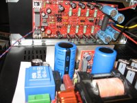
Quasar version 13i, powered by 1KW Quasar SMPS and with excellent R2R DanZup volume controller.
Mos-FET transistors are from Class-D (Semefab) and I must say that I´m really impressed by their performance.
Regards,
Tibi
Mos-FET transistors are from Class-D (Semefab) and I must say that I´m really impressed by their performance.
Regards,
Tibi
Attachments
Above links are no longer working, but you can get all documentation available at vicol audio : quasar - a quad 405 reborn
For those who want to make version12 of quasar, gerber files below attached.
Regards,
Tibi
a question. By what program I open these files?
then open them with winrar or winzip
They are Gerber files, necessary for professional PCB manufacture. You can download free Gerber viewer programs if you want to peek at the different layers, overlay, drilling guide files etc. Here is an example.
gerber file viewer | Free Science & Engineering software downloads at SourceForge.net
gerber file viewer | Free Science & Engineering software downloads at SourceForge.net
They are Gerber files, necessary for professional PCB manufacture. You can download free Gerber viewer programs if you want to peek at the different layers, overlay, drilling guide files etc. Here is an example.
gerber file viewer | Free Science & Engineering software downloads at SourceForge.net
One that is not only for display.
Do you mean you want a program to see all files?
Some will not be viewable - they're just data for machines, being numbers and characters.
If you have Google installed you can search many viewer programs.
Just type "Gerber file viewer" in the browser and go!
If you want a manufacturer to produce PCBs for you, those are the files you send,
assuming they are compatible with the manufacturer's software like Protel, Traxx etc.
- Home
- Amplifiers
- Solid State
- QUASAR a reborn design