How about capacitors ? Charge up a cap & then discharge it FULLY, & then watch the voltage rise. Not much i agree, but it does ! Also for eg, sample/hold caps don't retain their voltage forever.
I realise the above examples are pushing the envelope, pun intended, But still "maybe" worthy of consideration ?
Yes, I think a DA characteristic in a capacitor might qualify as a memory distortion mechanism, but it is unclear how big its effect would be and under what conditions it would come into play.
Cheers,
Bob
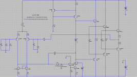
Please sim this with the component values in my design, if not with the transistors and models I used.
Hi Bob,
Here is the minor loop transmission simulation with your component values. Phase shift at unity loop gain is 192 degrees. Still unstable.
Attachments
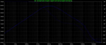
Bob, minor loop phase at unity gain with emitter resistor 192 degrees. (blue trace);
minor loop phase at unity gain without emitter resistor 185 degrees (green trace)
You can do the closed loop frequency response plot yourself if you wish; i've attached the file.
Here's the problem, Mike.
Every time you make an assertion about "my" amplifier having an instability, it turns out that it is not "my" amplifier. Stop making assertions about "my" amplifier until you simulate "my" amplifier. I have simulated my amplifier and have found that the presence of the emitter resistance DOES make a big effect.
You are making the assertion and you should demonstrate your assertion on the circuit you are making the assertion about. This is a reasonable starting point. If you want to assert that the Darlington cascode VAS can be unstable under your set of conditions you are welcome to do so.
Finally, and very notably, you yourself have demonstrated that the instability you are talking about is indeed visible in the closed loop response in spite of the fact that you previously asserted that it was not). This is important because it provides a sanity check on the loop gain probe. That's why I want you to demonstrate the presence of the instability in my design with a closed-loop simulation.
I will continue to investigate this on my design and will be happy to share the results. I am truly interested in finding the truth and any source of discrepency. All I want to do is get it right in my book and be able to explain what influences it. But you putting up bogus designs that don't represent my design is not helpful in converging this process.
Cheers,
Bob
Here's the problem, Mike.
Every time you make an assertion about "my" amplifier having an instability, it turns out that it is not "my" amplifier.
I think you posted before reading my posts above. I have done as you asked: changed degeneration resistors in the input stage to 470ohms; reduced standing current in the input stage to 1mA; reduced the compensation capacitor to 30pF; used TIS emitter degeneration resistor of 22ohms.
I took the trouble to do all these completely irrelevant things to demonstrate that they have virtually no impact on minor loop stability, except, of course, for the inclusion of the TIS emitter resistor which, as I have demonstrated, reduces minor loop gain in the audio band, but increases instability. See post 3222 above and post 3216 here:
http://www.diyaudio.com/forums/soli...lls-power-amplifier-book-322.html#post3507941
Now, Bob, can you post the results of your own closed loop and minor loop simulations please? I don't recall seeing any of your simulations posted.

Last edited:
This is precisely what I dispute: minor loop instability may not show itself in the amplifier's closed loop frequency response. I know this for a fact.
Could you show an example then.
As I predicted you said the Cordell circuit shows minor loop instability, and there you have it, it shows in the closed loop response.

Could you show an example then.
As I predicted you said the Cordell circuit shows minor loop instability, and there you have it, it shows in the closed loop response.
Yes. See below:
http://www.diyaudio.com/forums/soli...lls-power-amplifier-book-320.html#post3507209
If Bob & Mike are using the same circuit but with different semiconductors then differences in the predicted results must be down to the semiconductors' modeled parameters.
Are we sure the circuits are now the same?
Then the question becomes:
Which parameters are the major cause of the different results?
Are these parameters down to a bad model/s, or is the circuit very susceptible to the chosen transistors?
Are we sure the circuits are now the same?
Then the question becomes:
Which parameters are the major cause of the different results?
Are these parameters down to a bad model/s, or is the circuit very susceptible to the chosen transistors?
Last edited:
If Bob & Mike are using the same circuit but with different semiconductors then differences in the predicted results must be down to the semiconductors' modeled parameters.
Here is an example of someone who actually built and tested an amplifier with a cascoded beta enhanced TIS and found it to be intractably unstable:
Memory Distortion Philosophies - Part 8 : More tests
This together with my experience demonstrates that my Zetex models are sound.
Last edited:
Michael's .ASC, models etc ??
Michael, when I try & run your .ASC file with your BJT_models.txt, the LTspice craps out with 'Fatal Error: Analysis Failed: Matrix is singular'
If I remove one of the circuits, it still does the same thing.
Any suggestions on how to run your sim to completion? I really want to see for myself the effects you report ... so I'm using your models etc.
_____________________
What performance did you get? Stability?
There is no shame in distinguishing carefully between sims/theory that has experimental backing ... and that which is pure pontificating.
Pure pontificating has its place ... as long as we clearly understand what it is.
PS: I don't believe I've seen you post any circuits which you claim to have good performance though you have posted many purporting to be of other peoples that you say are faulty.
It's all very well to be critical of other people's work but to be constructive, how about posting something, preferably 'real word' that illustrates your ideas of good practice/THD/stability ?
Michael, when I try & run your .ASC file with your BJT_models.txt, the LTspice craps out with 'Fatal Error: Analysis Failed: Matrix is singular'
If I remove one of the circuits, it still does the same thing.
Any suggestions on how to run your sim to completion? I really want to see for myself the effects you report ... so I'm using your models etc.
_____________________
Are you saying that you have built amplifiers 'like' the .ASC models you have posted on this thread?This together with my experience demonstrates that my Zetex models are sound.
What performance did you get? Stability?
There is no shame in distinguishing carefully between sims/theory that has experimental backing ... and that which is pure pontificating.
Pure pontificating has its place ... as long as we clearly understand what it is.
PS: I don't believe I've seen you post any circuits which you claim to have good performance though you have posted many purporting to be of other peoples that you say are faulty.
It's all very well to be critical of other people's work but to be constructive, how about posting something, preferably 'real word' that illustrates your ideas of good practice/THD/stability ?
If Bob & Mike are using the same circuit but with different semiconductors then differences in the predicted results must be down to the semiconductors' modeled parameters.
Are we sure the circuits are now the same?......
According to the BJT model file Mike posted with #3222, the transistors in the TIS seem to differ quite a bit in the zero bias juction capacitances between Mike's circuit and that of Bob's:
ZTX1056A in Mike's simm
CJC = 53.1 pF
CJE = 508.6 pF
2N5551 in Bob's figure 3.13 circuit
CJC = 4.883 pF
CJE = 18.79 pF
They seem to be devices of very different construction although both were designed for switching applications.
I wouldn't say the circuits are the same.
Michael, when I try & run your .ASC file with your BJT_models.txt, the LTspice craps out with 'Fatal Error: Analysis Failed: Matrix is singular'
If I remove one of the circuits, it still does the same thing.
Any suggestions on how to run your sim to completion? I really want to see for myself the effects you report ... so I'm using your models etc.
I have no idea why your simulations are misbehaving; mine work just fine. You'll have to work it out yourself.
Are you saying that you have built amplifiers 'like' the .ASC models you have posted on this thread?
Close. But I never use the beta enhanced TIS.
PS: I don't believe I've seen you post any circuits which you claim to have good performance though you have posted many purporting to be of other peoples that you say are faulty.
It's all very well to be critical of other people's work but to be constructive, how about posting something, preferably 'real word' that illustrates your ideas of good practice/THD/stability ?
From my posts the astute should be able to deduce my design philosophy without difficulty. I cannot post my preffered circuitry in their entirety as they are to be published.
I think you posted before reading my posts above. I have done as you asked: changed degeneration resistors in the input stage to 470ohms; reduced standing current in the input stage to 1mA; reduced the compensation capacitor to 30pF; used TIS emitter degeneration resistor of 22ohms.
I took the trouble to do all these completely irrelevant things to demonstrate that they have virtually no impact on minor loop stability, except, of course, for the inclusion of the TIS emitter resistor which, as I have demonstrated, reduces minor loop gain in the audio band, but increases instability. See post 3222 above and post 3216 here:
http://www.diyaudio.com/forums/soli...lls-power-amplifier-book-322.html#post3507941
Now, Bob, can you post the results of your own closed loop and minor loop simulations please? I don't recall seeing any of your simulations posted.
Hi Mike,
You're right, I was responding to an earlier post of yours before I saw this one. Thank you for posting this closed loop simulation with my component values.
I have been doing many, many simulations yesterday and today, and I think I have discovered a big piece of the answer.
First and foremost, I have some egg on my face.
My amplifier, as originally published and simulated, had virtually none of the problem we are talking about here.
BUT, that work was done before I came up with my set of Cordell Models. To make a long story short, the absence of the problem in my simulation was faulty INDUSTRY models! Yes, isn't that ironic. When I re-did the sims of that amp with my own published models the peaking showed up; not as bad as yours, but noticeably there.
When I changed the models, I was desperately looking for anything that could be hiding the problem and causing the differences between our results. I replaced transistor models one at a time, starting from the input, then simulating closed loop response, which was a good indicator of this local instability. The MJE243/244 were the bad guys. I do now recall that the OnSemi models for them were particularly bad when I was doing my own models.
It is interesting, however, that this instability would be influenced to such a degree by the model of the center EF in a Triple. Moreover, even with my good 243/244 models, the degree of instability is greatly reduced by the presence of the output R-C Zobel network (8 ohms in series with 0.05uF).
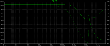
This instability phenomenon is quite sensitive to the impedance in the VAS collector circuit. In my circuit with my models, adding only 50pFto ground at that node reduces the peak from 6dB (at 36MHz) to a flat shoulder (no Zobel in place). This is happily less than the 200 or so pF you mentioned as necessary.
Even without the cascode, there is slight evidence of this instability, by the way. The lower output impedance of the non-cascoded VAS appears to be at least partly responsible for mitigating the instability.
Although I have not completed all of the simulations, it also appears that the Darlington cascode has little if any such instability when it is driving the heavier load of an output double, as compared to a Triple.
So to some extent, some of this instability may be attributable to a confluence of the cascode and the much lighter loading of the Triple (but, as mentioned above, even the Triple still allows mitigating influences in the output chain to have an effect).
Adding a 50pF load to the VAS is not the only cure. It turns out that adding a 100pF load to the output of the IPS current mirror also does the trick. My definition of doing the trick is to reduce the peak to less than 2dB.
Finally, and perhaps most interesting, is the following solution. Put a 100-ohm resistor in series from the emitter of the VAS EF to the base of the main VAS transistor AND connect a 10pF capacitor from the collector of the VAS cascode to the base of the main VAS transistor. This allows some bypass of high-frequency feedback directly to the base of the main VAS transistor. This scheme is nice because it introduces very little additional loading on the VAS output node.
A 100pF from base to emitter of the EF preceding the VAS transistor also mitigates the problem, but a bit less effectively.
There is probably more to this saga, but that is pretty much all for now.
The good news remains that this instability is visible in the closed loop response. This underlines the importance of observing the closed-loop frequency response of the amplifier out to 100MHz or so (without an input filter!).
A cautionary note is that some of this sort of thing might be possible even without the cascode, when an EF-VAS is used with a Triple output stage. Indeed, there is even a chance that some of what is going on here is partly playing a role in some instability that has been attributed to Triple output stages in some situations.
This may be linked to my preference for putting a series R-C (e.g., 100pF and 100 ohms) from the VAS node to ground even in designs where I am not using a cascoded VAS.
There still may be some interactions between the Triple and the Darlington cascode that go beyond simple loading of the VAS node.
Anyway, this has been an interesting journey, and I have learned from it.
Cheers,
Bob
In respect of the rest of the amplifier, such distortion, if it exists at all, would also exist at very low frequecies. So, why isn't it detectable even in an amplifier of even moderate competence?
Because other distortions dominate. Although according to Bob, this is not in all cases.
There is no point in eliminating solutions before one even has a problem. It would go against physics to say that this kind of distortion doesn't exist because we know that die temperature modulates semiconductor behavior.
That is behavior nonlinear in function of temperature, but this will not always bring distortion, for example: Transistor hot has more gain and you may have less distortion.
The physical phenomenon of a component store energy not called "memory".
yet another useful stability tweak ..
___________________
This is to decouple the VAS emitter resistor with 1n or something smaller.
I have this from late 80's when trying to make 'pure Cherry' work. It is essential to that technique especially when applied to 'enhanced VAS + EF2' but is useful with other compensation methods too as it directly targets the 'inner loop' [*] while keeping the VAS output clean.
I've done some sims with Michael's #3170 circuit. As this is not a complete amplifier ... no load, no Zobels, output inductor, some strange choices of currents, resistor values & operating points etc ... it is likely that it would be unstable with 'real life' loads and have poor THD.
However, it IS an 'enhanced VAS + triple' so might be worth looking at. I'll post tomorrow.
If you have a working .ASC of your latest sim, I would much appreciate a copy.
I have to declare my prejudice against evil triples, and any compensation that besmirches the Holy HiZ of the VAS output .. ie practically all methods except 'pure Cherry'. The problems you describe are responsible for some of my dislike of triples and evil fancy VAS, IPS etc. Hence my search for simple stuff that will do 1ppm THD @ 20kHz
[*]Even plain Miller around a single BJT VAS has an 'inner' loop.
I finally traced the problem to an extra Line Feed/Newline in one of the BJT_models.txt that you provided. Your models now work.michaelkiwanuka said:I have no idea why your simulations are misbehaving; mine work just fine. You'll have to work it out yourself.
___________________
Bob, if I may suggest yet another 'cure' ...This instability phenomenon is quite sensitive to the impedance in the VAS collector circuit. In my circuit with my models, adding only 50pFto ground at that node reduces the peak from 6dB (at 36MHz) to a flat shoulder (no Zobel in place). This is happily less than the 200 or so pF you mentioned as necessary.
... loadsa good stuff ....
There is probably more to this saga, but that is pretty much all for now.
... more good stuff ....
A cautionary note is that some of this sort of thing might be possible even without the cascode, when an EF-VAS is used with a Triple output stage. Indeed, there is even a chance that some of what is going on here is partly playing a role in some instability that has been attributed to Triple output stages in some situations.
This is to decouple the VAS emitter resistor with 1n or something smaller.
I have this from late 80's when trying to make 'pure Cherry' work. It is essential to that technique especially when applied to 'enhanced VAS + EF2' but is useful with other compensation methods too as it directly targets the 'inner loop' [*] while keeping the VAS output clean.
I've done some sims with Michael's #3170 circuit. As this is not a complete amplifier ... no load, no Zobels, output inductor, some strange choices of currents, resistor values & operating points etc ... it is likely that it would be unstable with 'real life' loads and have poor THD.
However, it IS an 'enhanced VAS + triple' so might be worth looking at. I'll post tomorrow.
If you have a working .ASC of your latest sim, I would much appreciate a copy.
I have to declare my prejudice against evil triples, and any compensation that besmirches the Holy HiZ of the VAS output .. ie practically all methods except 'pure Cherry'. The problems you describe are responsible for some of my dislike of triples and evil fancy VAS, IPS etc. Hence my search for simple stuff that will do 1ppm THD @ 20kHz
[*]Even plain Miller around a single BJT VAS has an 'inner' loop.
why does it seem the fundamental principle of global negative feedback is often overlooked in these hypotheticals about memory, thermal distortions
it is simply fact that high loop gain reduces ALL errors measured by the feedback network&diff input - by the excess loop gain at the error frequency - so IMD folding down, or low frequency thermal modulation after the diff pair - ALL are going to be reduced by the excess loop gain
high feedback == all feedback loop measured distortions reduced by big factors
jcx, have we not treated thermal distortion like any other distortion mechanism?
Also, saying loopgain increases linearity is oversimplified and leads to tears. There are plenty of ways to increase loopgain that do the opposite. The open-loop linearity is divided by loopgain, so linearity and loopgain equally contribute to THD; it's not one-sided. Another way of saying it is that distortion is not always loopgain deficiency.
The input stage is one example where loopgain may or may not help. C-B leakage is a source of distortion, as well as Early effect, and the CMRR does not go away with loopgain. These distortions either need rejected (cascoding) or swamped (low feedback network impedance). This applies to thermal distortion as well (offset being one example).
Because other distortions dominate.
Not true. If other distortons dominate, why is it possible to routinely design amplifiers with less than 7ppm THD at LF?
On the contrary, you need to avoid the sticky pseudo science trap of inventing solutions to non-problems.There is no point in eliminating solutions before one even has a problem. It would go against physics to say that this kind of distortion doesn't exist because we know that die temperature modulates semiconductor behavior.
Thermal distortion, which has nothing to do with this new fangled "memory distortion", only occurs in detectable quantities in monolithic op amps whose input stages are heated by the output stage. see below:
http://ece.wpi.edu/~mcneill/524/handouts/solomon.pdf
Last edited:
Bob, if I may suggest yet another 'cure' ...
This is to decouple the VAS emitter resistor with 1n or something smaller.
Shunting the TIS emitter resistor capacitively works because, contrary to Cherry, that resistor only increases the tendency to instability in the minor loop.
The capacitor introduces a zero in the minor loop transmission before unity gain, and merely demonstrates that Cherry was wrong to recommend the inclusion of this resistor as a stability enhancer.
- Home
- Amplifiers
- Solid State
- Bob Cordell's Power amplifier book