I'm not that into this PCB layout thing as Alex MM or many others here... Anyway, I completed a first shot of what it's gonna look like 

PCB size is 367x103mm² now, perfectly fitting into the case planned for it
@Walkalone: I assume you pointed to the ground track on the right side of the PCB? And I will have a look into the M2600 manual, always willing to learn. Thank you.
BR,
Holgi

PCB size is 367x103mm² now, perfectly fitting into the case planned for it
@Walkalone: I assume you pointed to the ground track on the right side of the PCB? And I will have a look into the M2600 manual, always willing to learn. Thank you.
BR,
Holgi
Not any relevance? Oh, let's resume...
- schematics match the original with the exception of giving discrete darlingtons a try
- feedback to my posts is rather positive, at least I would call it that way
- nobody is confused in any way by now, or did I miss something?
I don't know what's your point here. But anyway, since I'm new to at least this DIY forum I will leave this topic private to you, your design and the considerations others make to optimize your design. Sorry for taking the design for attractive enough to give a slightly modified design a try...
Leaving this topic now, thanks to the feedback received so far.
astx, your output transistor protection is very poor indeed. See paper here:
http://www.diyaudio.com/forums/solid-state/235841-michael-kiwanukas-soa-paper.html
http://www.diyaudio.com/forums/solid-state/235841-michael-kiwanukas-soa-paper.html
astx, your output transistor protection is very poor indeed. See paper here:
http://www.diyaudio.com/forums/solid-state/235841-michael-kiwanukas-soa-paper.html
Dear Michael,
thank you for demanding me to this topic and thank you for your SOA informations. A LTspice simulation like figure 47 is running but needs time to get a working SOA protection as shown in figure 27/28.
In post #37 there is the detail information that the amplifier is NOT short circuit proof.
Maybe you are able to help here with a basic calculation?
BR, Toni
- would a 10n BE-cap on every driver improve sound/stability?
That would make them slower than the outputs! Perhaps 470p would do, and include the degeneration in the bypass. This will improve Ft consistency at transients and may help with square waves by limiting Ft to a certain value regardless of Gm spike. However if the transistor turns off that cap will draw a significant current. This idea should be investigated.
IMLE, hobbling transistors in the forward path this way kills the slew rate, overload recovery and THD. It is a very bad way to 'cure' stability problems and usually makes it worse.
- would a 10n BE-cap on every driver improve sound/stability?
10n on the drivers is HUGE
That would make them slower than the outputs! Perhaps 470p would do, and include the degeneration in the bypass. This will improve Ft consistency at transients and may help with square waves by limiting Ft to a certain value regardless of Gm spike. However if the transistor turns off that cap will draw a significant current. This idea should be investigated.
You're right, 10n would be too much there. Intention was indeed to enhance square wave behaviour. Will play around a little, thank you!
Overload Recovery
Some of you may have guessed that Overload Recovery is one of my pet obsessions.
The 'pure Cherry' version I posted in #182 was extensively tested.
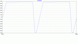
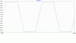
Imagine my horror to find the 'pure Cherry' version of Toni's #274 behaved as below ... at least in SPICE world. It takes forever to come out of +ve saturation. 1837_aVAS.gif
Much investigation later, the cause was traced to the 'new' 2sa1837/c4793_a used for main VAS & its CCS load. It appears that when these saturate, Ccb goes to very high values and has to be discharged before the amp comes out of +ve saturation.
Going back to 2sa1930/c5171_d models 'cured' this. These are Harry Dymond's models. Harry has several caveats about his models. 1930_dVAS.gif
Dunno where the 2sa1837/c4793_a models are from but both are in Toni's mylibs.lib
The sim pics are from Toni's #274 TMC .ASC The 'pure Cherry' versions are similar.
Toni, can you see what overload behaviour your amp has in 'real life'?
It would be nice to get the BJT models to reflect something of 'real life' behaviour but I'm not a SPICE model guru
These are output pics with 20kHz 3.85Vp input
Attachments
Last edited:
Toni, can you see what overload behaviour your amp has in 'real life'?
It would be nice to get the BJT models to reflect something of 'real life' behaviour but I'm not a SPICE model guru
These are output pics with 20kHz 3.85Vp input
Simulations shows incorrect data at 20kHz. In simulation it looks like it does take veeeery long time to come out of saturation. Not so bad in real life: if you simulate 1kHz overload then you get a plot which looks like real life 20kHz oscilloscope picture. Real life lower frequency overloads are simply truncated sinus waves.
BR, Toni
Hi "manso"
I have had a think about this and wonder why you think the gain will be lower?
Does not seem consistent with my analysis or Toni's result below.
David
It may be if the transistor used enters quasi-saturation, because of lower Vce.
When testing the actual amplifier for clipping behaviour and/or how it comes out of clipping, should one attach a resistive load?
What value of resistive load?
Do we need to also check with a slightly reactive load?
It may be if the transistor used enters quasi-saturation, because of lower Vce.
Increased current mirror emitter resistors do not alter the transistor Vce if the mirror is balanced, the whole current mirror just sits a bit further from the rails.
Toni's mirror is fairly well balanced so unless I am mistaken, your comment does not apply here.
Best wishes
David
Last edited:
- Home
- Amplifiers
- Solid State
- 2stageEF high performance class AB power amp / 200W8R / 400W4R

