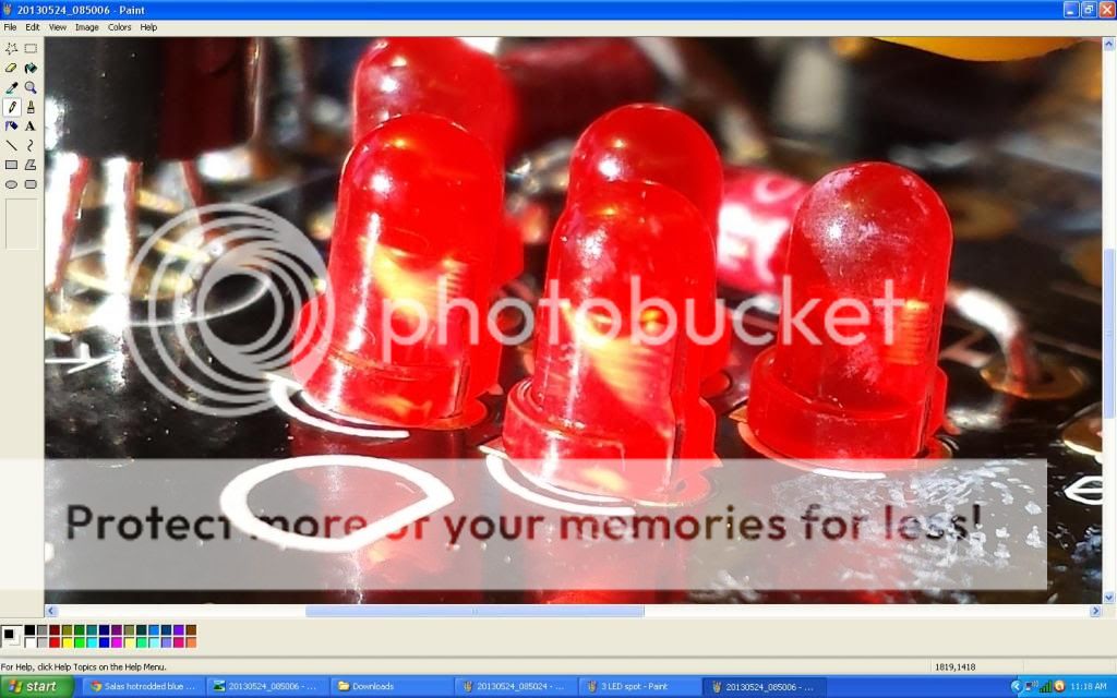
you can measure the Vdrop on each LED from the underside.
They should ALL have the +ve voltage towards the rounded side of the LED package.
If one LED is reversed then it will have the whole voltage across it and the others in the group will have near zero volts drop.
A reversed LED is a reversed Diode, but with a very low blocking capability. The LED breaks down to never recover when too much reverse voltage is applied.
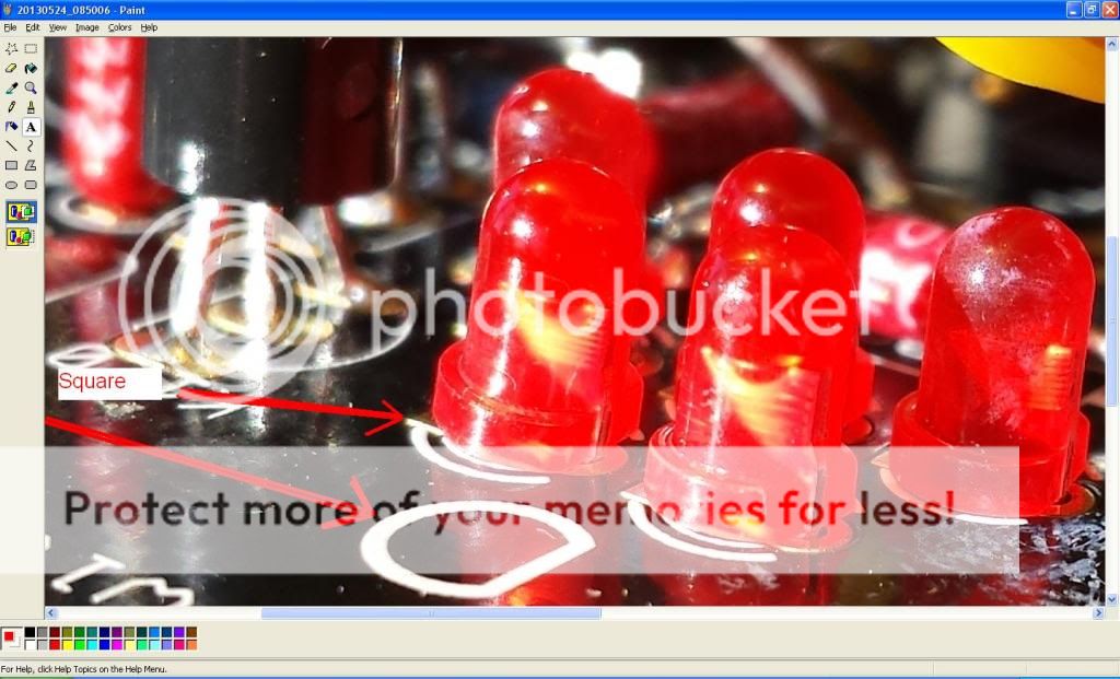
They look in right direction to me.
I would wait. Test each bulb with diode tester first. needs to light up.
I'm confused Tea-Bag.
The LED Orientation image on the PCB has the Anode (+) going into square and in a prior post you mentioned "general rule of thumb for CRT boards is anode in round hole cathode in square hole. "
Take a look at my zoomed in image of the 5 LED spot and you can see.
I appreciate all the help...
My impatience got the best of me and I trashed my DCB1 board... I was soldering out LEDs and swiching and putting back in.. The solder traces came out and the heat / solder got deep between (-) and (+) LED spots on the PCB.
I had trouble pulling them out and going back in... Got the board WAY too hot... On 3 spots the board area of the 5 LED is trashed. The LED square/circle solder traces came off and plastic in the holes... Real bad
I got in a hurry. I took a day off from work and I have to get the kids soon. rushed.
I was close....
Does anyone sell a completed DCB1 that was built with the standard kit PCB and parts?
Be a little patient and repair the board is my 2C. Invest that new kit money for a controlled soldering station and a desoldering pump. So you can work much better for all future projects or repairs. The Hakko FX888 station is particularly cheap in the US for instance.
One thing I did notice... I am thinking my LEDS may not have been the real problem after all this..
The two sets of 3 LEDS would light when powered.. When the power was cut the one set of 3 would turn off right away.. The other set of 3 LEDS would dim over about 5 - 7 seconds like the power supp. caps were slowly draining. Also, the main two resistors from the power supp caps to the LEDS would get hot and quick
The two sets of 3 LEDS would light when powered.. When the power was cut the one set of 3 would turn off right away.. The other set of 3 LEDS would dim over about 5 - 7 seconds like the power supp. caps were slowly draining. Also, the main two resistors from the power supp caps to the LEDS would get hot and quick
You got to probe and see if every MOSFET has ~4V VGS for instance. (Between outer pins). If not, its dead or wrong put when all other things are correct. One thing they had done wrong maybe one or two guys in the past was to put the negative side MOSFET type to the positive side. I.e. confirm all semiconductors are in the right place by type and orientation. Check electrolytics orientation even.
In one of my earlier builds I had issues with the 3 led groups - turns out it was way I installed my mosfets - they were all attached to the same aluminum heatsink without any silpads. Sometimes I would get lights if I touched mosfets and I would blow a fuse - I also had to up my fuse values, it was not anywhere near value in the BOM.
Here is that strange thing with the 3 LED sets... when I apply power I get both of the 3 sets to light... When I cut power the one set turns off right away while the other is slow and drains the 10000uF caps
http://s1134.photobucket.com/user/amanthey/media/20130525_073840_zps87d75816.mp4.html
http://s1134.photobucket.com/user/amanthey/media/20130525_073840_zps87d75816.mp4.html
- Home
- Source & Line
- Analog Line Level
- Salas hotrodded blue DCB1 build