Give this a try and see what you think:
Mullard Tube Circuits for Audio Amplifiers: Mullard Technical Serv Dept: 9781882580033: Amazon.com: Books
All good fortune,
Chris
Mullard Tube Circuits for Audio Amplifiers: Mullard Technical Serv Dept: 9781882580033: Amazon.com: Books
All good fortune,
Chris
Rene -
Good point about the transformer winding considerations. I will certainly be seeking to have a good conversation with any custom winder before having them start on the work. The transformer design factors will surely play in to the final configuration selected.
Chris -
Thanks for the reference, I've ordered a copy. The Hafler & Keroes article, figure 2, does show a minima for high-level IMD, which happily coincides with the knee of both the low-level IMD and internal impedance curves, and is still within the higher power output region. Based on the data presented, I agree with their choice. IMD and internal impedance will likely dominate my own eventual choice, just for a different tube and operating point. Looking forward to the Mullard book.
Cheers,
Chad.
I know it is indecent to refer to something without being able to quote a reference, but I simply cannot now find my www reference for the following.
There are very interesting UL graphs for the KT88 by G.E.C., showing performance with G2 tap from zero to full triode operation (will post here when I find; see time of night!) There it shows that there is no ultimate optimum. The maximum available output starts decreasing just below 50% taps (from memory), while rp goes down all the time as well as %D until they approach triode values. (Here one must be careful. The distortion amplitude falls more than shown as the g2-tap-% increases, because the distortion is a % of an ever decreasing maximum output.)
I found that the KT88 graphs are generally applicable to beam tubes, while different graphs I saw somewhere for the EL34 applied rather more generally for normal pentodes (again apology for not being able to quote)..... well, when said 'normal pentodes', they were EL34 and EL84, both high-gm tubes.
I have done some work on using the whole section {G2 - B+} as cathode winding. As said, the drive needed gets pretty severe. In my work I used 4 x 6L6GCs in p.p. parallel for 110W output; 600V h.t. to anodes and 500V stabilised to g2s and the rest of the circuit. For 33% taps I required a rather severe signal drive of 390Vpp (which I got from E182CCs with moderate distortion). With 25dB of global NFB the distortion at 100W was just over 0,13%.
Reducing the cathode windings to some 24% (full winding layers) I could still get distortion below 0,17% while easing the demand on the E182CCs. The transformer required some inter-sectionalising of primaries apart from the usual several secondary sections because the operation was quite class AB. [The above figures were for fixed grid bias, but cathode positive rather than grid-1 negative for other reasons, thus rather like an active "cathode-zener". The final OPT was wound on a double loop of 500W (at 50 Hz) C-core.]
These figures to give some idea of what could be expected at the levels indicated, not necessarily optimal. As said there is no sweet optimal set of values.
prairieboy:
Thanks for the tip on Vixen. Unfortunately, having tried to search, I haven't yet turned up the description regarding plate choke purpose and winding method that you mentioned. It seems Mr. Prower is a rather prolific poster... my searches have either turned up nearly nothing, or hundreds of results! If possible, could you point me to the specific thread / site? ... or in lieu of that, a synopsis of the salient points would be nice.
Surprised Miles hasn't jumped in yet, but since he hasn't, I think this one covers the major points:
http://www.diyaudio.com/forums/tubes-valves/93612-higher-power-amps-using-807s-1625s.html
JLH:
The drive requirements do indeed get a bit silly with excessive CFB. Interesting comment about perveance - makes sense. What, in your estimation, counts as a "high perveance" tube (it's not a commonly listed spec)? Pretty much all the usual 6L6-oid power pentodes? Just looking at transconductance as a stand-in, I see the 6550 and EL34 look to be roughly double the gm (and appear to have larger cathode areas) of the 7027A.
High perveance as in high Gm and Mu. If you look at the data sheets for the majority of pentodes designed for sweep use, they normally list Gm and Rp. From this you can calculate the pentode's Mu. I normally look for Gm higher than 6mA/V and Mu greater than 85
Johann,
Are you recalling Amplifiers and Superlatives - Williamson/Walker - Wireless World, September 1952?? Warmly, Graeme
Hi Graeme! Long time ... !
Yes, it resides here in my files; haven't read it for a while.
To all,
I found the graphs I mentioned before in a publication at ultra-linear
It is a long article, with the graphs roughly 66% down. This is not the article I recalled but the graphs are the same, indicating the UL-use of KT88s under various loads and tappings.
(Edit: Typo)
Last edited:
One my friend did OPT with CFB for himself (diy OPT), he use it for 811A SE amplifier. Sound is great on warm, sweetness and control bass when compared to one without non CFB.
How much CFB winding is reasonable ? Some OPT have 16 ohms impedance of CFB winding or more, other has 12 ohms ?
Some use secondary winding to be CFB, Is it OK and safe ?
How much CFB winding is reasonable ? Some OPT have 16 ohms impedance of CFB winding or more, other has 12 ohms ?
Some use secondary winding to be CFB, Is it OK and safe ?
Attachments
One my friend did OPT with CFB for himself (diy OPT), he use it for 811A SE amplifier. Sound is great on warm, sweetness and control bass when compared to one without non CFB.
How much CFB winding is reasonable ? Some OPT have 16 ohms impedance of CFB winding or more, other has 12 ohms ?
Some use secondary winding to be CFB, Is it OK and safe ?
Do not think of CFB in terms of impedance. You need to think of it as a voltage ratio, or turns ratio. A 3K output transformer will have a different turns ratio (voltage ratio of CFB) on its 16 ohm tap than a 5K output transformer. Generally speaking, 15% of the primary turns is optimal for most tubes. Any more than this and you reach a point of diminishing returns where the reduction in Rp gets over ran by the need for excessive grid drive voltage.
A 811A normally has an Rp around 26K, Mu 115, and Gm 4.4mA/V. With 15% CFB it turns into a tube with an Rp of about 1440 ohms and Mu 5.9 However, the drive voltage requirement goes from 40Vp-p to 186Vp-p. With 20% CFB the drive requirement jumps to 248Vp-p and Rp only drops an additional 345 ohms. The point of diminshing returns has been meet.
Last edited:
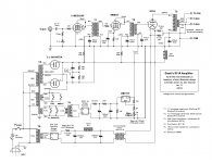
Howdy, All: Following Johan's lead, here is a link to one of the references I've used in connection with posts to this thread.
3 points:
Please take note of the use of impedance ratios and not voltage ratio, in the article. I don't agree with that, voltage ratios are much more useful, I'm simply pointing out that that is what many authors commonly used then.
This article clearly shows an optimum point
The experiments were done in such a way to make sure the results are due to the tapping choice, as the operating points and load impedances were reset as necessary as the tapping point changed, in order to maintain the tubes within proper limits.
The link: Tetrodes with Screen Feedback
... after a two week hiatus due to business travel, I have decided I will look into ordering a custom measurement transformer, with a tapped tertiary instead of tapped primary.
The objective will be to set up a semi-automated measurement system and let a computer chug through data collection over a wide range of bias conditions, load impedance, output power, and screen tap ratio. Basically, map the whole space of operating conditions and get something more like a set of multiple 3D contours instead just a few 2D curves. This will be straight-up fixed bias ultra linear configuration - no CFB. Once a sweet spot is found for the tube operating point, the winding impedances and ratios can be separately calculated for the addition of CFB.
Thoughts? Suggestions?
The computerized measurement setup is going to be quite some effort, so I'm going to have to be careful to keep it manageable and not get too complex.
I'm going to put in an inquiry with the transformer winder and see what kind of cost is involved. If anyone else is interested in acquiring a similar measurement transformer, let me know. I'm not up for hosting a big group buy, but if a few others are interested, it could help bring the cost down a bit.
Chad: since this is an experimental transformer (if I read the post correctly) and not a final product, you might want to consider the P-P winding and the additional screen and tapped winding and no load secondary. Rather, apply the load directly P-P and set that load's value per your experiment matrix. All this will reduce the cost of making the transformer a bit and eliminate leakage inductance issues between plate and load windings, though the less than perfect coupling between plates and screens remains as an issue.
Another course could be to use a plain P-P transformer and resort to MOSFET circuitry to simulate the screen tapping, which will let you apply all the screen grid variables you'd otherwise be able to apply using the tapped screen winding. Two caveats: one is, mind the supply voltage to the MOSFET drain, must be enough to handle the upswinging plate at the selected tap percentage and, two and most thought provoking: the screen, using this method, no longer contributes to the output power. It should still allow you to determine points of best bias and load to translate to the final transformer product. Tubelab George came up with a clever scheme using ORing diodes to feed the MOSFET drain from either the corresponding plate when upswinging or a convenient +B when down swinging. Still does not contribute to the total delivered power but makes it more likely you won't have supply level issues.
The other thought I'm having is that the implementation of CFB on top of what you learn without it, may have a bit of an unknown dimension in that the CFB will alter the circuit's plate resistance vis a vis no CFB. If you have a good way of accounting for this for the final transformer, I'd say you have a great plan!
Will you be sharing your computer data correlation program?")
Good luck!
Rene
Another course could be to use a plain P-P transformer and resort to MOSFET circuitry to simulate the screen tapping, which will let you apply all the screen grid variables you'd otherwise be able to apply using the tapped screen winding. Two caveats: one is, mind the supply voltage to the MOSFET drain, must be enough to handle the upswinging plate at the selected tap percentage and, two and most thought provoking: the screen, using this method, no longer contributes to the output power. It should still allow you to determine points of best bias and load to translate to the final transformer product. Tubelab George came up with a clever scheme using ORing diodes to feed the MOSFET drain from either the corresponding plate when upswinging or a convenient +B when down swinging. Still does not contribute to the total delivered power but makes it more likely you won't have supply level issues.
The other thought I'm having is that the implementation of CFB on top of what you learn without it, may have a bit of an unknown dimension in that the CFB will alter the circuit's plate resistance vis a vis no CFB. If you have a good way of accounting for this for the final transformer, I'd say you have a great plan!
Will you be sharing your computer data correlation program?
Good luck!
Rene
Hi Rene,
I had similar thoughts about the load winding and leakage inductance - didn't think about omitting the load winding entirely, but did consider a higher impedance winding than 8 ohms might result in better coupling. Two things come to mind: First, the AC voltage needs to be brought down to a safe level for the audio analyzer / sound card. Second, although it's simple to resistively attenuate the AC level, HV isolation is also nicely taken care of with a separate winding. It might even be nice to listen and/or test with a real loudspeaker, but that's a lower priority so I'll see what the winder thinks.
I read through some of that adjustable distributed load thread, and caveat #2 that you mention is precisely why I've decided not to go the active g2 drive route. The diode supply scheme potentially suffers commutation effects that I'd rather not add into the mix at this point. I also believe that the g2 output power is significant, and could well be contributing substantially to the distortion reduction seen with UL operation. To my mind, the goal is first to enable (but not preclude) the design of optimized transformer configurations that don't require solid state embellishments. Also to keep things focused and simplified, I will eschew these complications, at least at first.
The CFB effects, as I understand, are relatively orthogonal to the UL% and bias point considerations. Pretty much all it should do in the end is apply local NFB around the output tubes, and subtract some turns from the anode and screen windings. The lower Rp can be thought of as the result of NFB. I'm sure this is a simplification, but it's an approach that I think should work well and help separate the variables, at least to the first order.
Cool, Chad, it shows that you are not proceeding, as the Great Pogo used to say, "onward through the fog!". Here is a bug in your ear: how about, after you've obtained the data via your outlined methodology, inserting the MOSFET circuitry and empirically determine how that approach may differ in its results. There is a bit of a selfish motive. I am in the early process of designing an amp, about 50W or so per side, using sweep tubes, most likely 6CB5, which need a much lower G2 supply level than "regular" tubes. This means either a tertiary, zeners from the taps or the MOSFET treatment for UL operation. As an old hand at designing and building transformers, if the tapping/tertiary winding may be avoided, I'm for that.
Brings me to one more input for you. You may want to have a small gage "load" winding for the instrumentation, placed where its coupling is best to the primary, and then a more usual load winding for your dummy or speaker load. As you say, talk with your winder, much will depend on what is comfortable for him. Certainly your observation that a higher number of turns for the load secondary will improve coupling is correct. Maybe from there, for crude listening tests, you may employ yet another transformer to better couple your high impedance secondary to your speaker load. A lot of relief is offered to this second transformer, though it will still be another magnetic coupling device in the path. Ah, the tradeoffs we must endure in engineering!
Again, best of luck, hope you make some really cool discoveries! You did not answer the question of whether you'll be sharing your computer program with us
Rene
I absolutely do intend to experiment with FET drive for g2 at some stage. But, baby steps first.
The gage winding is an interesting idea, I'll add that to my notes. Always the tradeoffs...
As for the software, well, I will have to think about this - it may depend on whether or not I'm too embarrassed to show my amateur code and/or my ability to support it. I'm a hardware engineer, and really only dabble in software from time to time. I will probably be writing this mostly in python, and will be leveraging some existing code I've already written to control some of my lab equipment via enet / gpib. The end result is likely to be a mishmash of scripts customized to my personal equipment and temporary test lashups, so I doubt it will be generally useful for others. But, we'll see what comes out of it. I'm already working on some python based sound card capture + FFT + distortion analysis code - this piece of it could be broadly applicable.
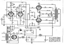
Folks - and I am sure this is repetition, but lazy to read back ... one must just keep in mind that the CFB winding is part of the UL configuration; it forms part of the winding between screen and B+. Thus ideally all of the winding from 'G2 - B+' may form the cathode winding part, in which case the screen is also free to go to a lower voltage supply (Quad II). I have done this, only the grid drive signal amplitude becomes prohibitive. I have settled for a 25% winding, in other words 'tap', making matters feasable at some 500+V h.t. (Using 6L6GCs and high-gm drivers, 0,1% THD is within reach this way. But think I am repeating.)
Nevertheless, I am following this with interest. The "Wireless World" article and figures by Langford-Smith is also most informative (seems to contradict the GE-KT88 results somewhat, but two different tubes.)
Just one small further matter: Giving distortion as % of total output. The actual distortion products go down as the available output decreases, thus constant % figures do not mean constant distortion amplitude. At a stage these might go below the threshold-of-hearing. I did not try any calculations regarding this, but it might be useful to keep it in mind.
OK, Chad, you found me out. I, too, am a hardware engineer with expertise in high temperature down-hole design of analog, magnetics and power circuitry. My code writing is limited to assembly and C. period. Soooooo, when you mentioned a PC run program....
I'm very glad to hear that adding the MOSFET G2 drive to your experiment matrix at some point, please keep posting on this thread.
Johan, I very much agree with you that the LS vintage article was so helpful. It helped me immensely in forming my view that there is no classic NFB phenomema involved in UL operation but rather, it is the dynamic modification of the tube's transconductance due to the constantly changing G2 voltage as a function of the instantaneous plate voltage.
OK, past my time to turn in while Johan must be having his morning coffee right about now.
G'night, Y'all!
Rene
- Status
- This old topic is closed. If you want to reopen this topic, contact a moderator using the "Report Post" button.
- Home
- Amplifiers
- Tubes / Valves
- UL / Distributed Load - Screen vs. CFB Winding Ratios