My scope is a Tektronics 465B. I have an even older 561B ith 10uV/1MHz resolution. The FG504 is something different:
Tektronix FG504 Square Triangle Sine Function Generator
40MHz max. Sa, sine triangle and square functions. Linear and log frequency seeps. VCF. I think I could broadcast FM if I hooked up a microphone!
Tektronix FG504 Square Triangle Sine Function Generator
40MHz max. Sa, sine triangle and square functions. Linear and log frequency seeps. VCF. I think I could broadcast FM if I hooked up a microphone!
My scope is a Tektronics 465B. I have an even older 561B ith 10uV/1MHz resolution. The FG504 is something different:
Tektronix FG504 Square Triangle Sine Function Generator
40MHz max. Sa, sine triangle and square functions. Linear and log frequency seeps. VCF. I think I could broadcast FM if I hooked up a microphone!
I have DIY function generator working up to 100kHz, sine triangle and square.
For inspecting amplifier stability you need something ith a fast risetime and high frequency capability. My FG504 has a 6nS risetime. ith 100KHz max you are only seeing very basic stability. There may be all sorts of nastiness you don't see.
You can make something like this:
http://www.diyaudio.com/forums/soli...as-lateral-output-perfect-44.html#post2773967
Use fast small-signal transistors like the 2N5089, BC550C etc. MPSH81 are great. Output ill be roughly 600mV, balanced, and ith the 27R resistors roughly terminated into a 50R coax cable. Poered by a 9V battery. 200KHz is about the right frequency for examining output impedance. To do this, put a 1k resistor in series ith the generator and hook it across the output of the amp, probing the amp output ith the scope. You should see spikes, and little ringing. Don't blo it up.
For inspecting amplifier stability you need something ith a fast risetime and high frequency capability. My FG504 has a 6nS risetime. ith 100KHz max you are only seeing very basic stability. There may be all sorts of nastiness you don't see.
You can make something like this:
http://www.diyaudio.com/forums/soli...as-lateral-output-perfect-44.html#post2773967
Use fast small-signal transistors like the 2N5089, BC550C etc. MPSH81 are great. Output ill be roughly 600mV, balanced, and ith the 27R resistors roughly terminated into a 50R coax cable. Poered by a 9V battery. 200KHz is about the right frequency for examining output impedance. To do this, put a 1k resistor in series ith the generator and hook it across the output of the amp, probing the amp output ith the scope. You should see spikes, and little ringing. Don't blo it up.
Thanks, I will need a time to make it, and the time is something you miss when retired.
Dado,
Please provide PCB Pdf files.
Joshvi
Did you ever make this amp??
dado
Not everyone is following the Analog Line Level thread, and interested for a line preamp I did one here http://www.diyaudio.com/forums/anal...onveyor-voltage-amplifier-12.html#post3343117 perfect conpanion for the TT amp described here.
dado
dado
Dado,
I want to make this one.But later, because I am busy with my job and have 2-3 projects in my hand.I think this one is worth to make.I have most of the components except VAS transistors.Instead of ksa1381/c3503 I have 2sa1360/c3423, can I use it ? I brought these for my fc100.
joshvi
I want to make this one.But later, because I am busy with my job and have 2-3 projects in my hand.I think this one is worth to make.I have most of the components except VAS transistors.Instead of ksa1381/c3503 I have 2sa1360/c3423, can I use it ? I brought these for my fc100.
joshvi
Dado,
I want to make this one.But later, because I am busy with my job and have 2-3 projects in my hand.I think this one is worth to make.I have most of the components except VAS transistors.Instead of ksa1381/c3503 I have 2sa1360/c3423, can I use it ? I brought these for my fc100.
joshvi
Yes, you can use it.
It would be very interesting to compare this one with fc100.
dado
Just came across this. As I have a bunch of military grade matched dual n junction FEts
( indeed the match is perfect, has two separate chips in one case) and low noise, too,
any idea how to reduce this amp to one pair of Thermal track? I don't need more than 60-80 watts peak power.
Thanks
( indeed the match is perfect, has two separate chips in one case) and low noise, too,
any idea how to reduce this amp to one pair of Thermal track? I don't need more than 60-80 watts peak power.
Thanks
Just came across this. As I have a bunch of military grade matched dual n junction FEts
( indeed the match is perfect, has two separate chips in one case) and low noise, too,
any idea how to reduce this amp to one pair of Thermal track? I don't need more than 60-80 watts peak power.
Thanks
Just to remove one pair of the output transistors you will loose two TT diodes I used between drivers emitters. I am not sureabout thermal behavior because it influence thermal stability. Look here http://www.diyaudio.com/forums/solid-state/221901-little-gem.html, but I did not build the TT version only with normal output transistors.
Last edited:
dadod,
I have studied the schematic of MK2 in this post: http://www.diyaudio.com/forums/solid-state/182554-thermaltrak-tmc-amp-3.html#post3065943
I must say I am impressed. There are so many small details to learn from.
This is a great project!
I hope more people will decide to build it.
Regards")
I have studied the schematic of MK2 in this post: http://www.diyaudio.com/forums/solid-state/182554-thermaltrak-tmc-amp-3.html#post3065943
I must say I am impressed. There are so many small details to learn from.
This is a great project!
I hope more people will decide to build it.
Regards
dadod,
I have studied the schematic of MK2 in this post: http://www.diyaudio.com/forums/solid-state/182554-thermaltrak-tmc-amp-3.html#post3065943
I must say I am impressed. There are so many small details to learn from.
This is a great project!
I hope more people will decide to build it.
Regards
Thank you lineup.
Best regards
Damir
TMC simulation
Hi Damir,
in the thread on Douglas Self's book, where you posted your TPC/TMC 'toy' amplifier, if have placed a remark to your way of evaluating the loops. I post that here again because you indicated that you unsubsrcibe the thread.
I would be really interested to solve the question how to cleanly evaluate *all* loops in a TMC design (the TPC part is then only a minor change).
http://www.diyaudio.com/forums/soli...-self-wants-your-opinions-62.html#post3454170
BR,
Matze
Sorry I did not answer your question sooner, I was busy doing Spring works in my garden.
This simulations are of my working TT amp, stable and playing for more than a year now.
First how you do the simulation here http://www.diyaudio.com/forums/soli...lf-wants-your-opinions-62.html#post3454170(of what?) is wrong. You should not use 1F capacitors to shorten negative input to the ground together with Middlebrook probe.
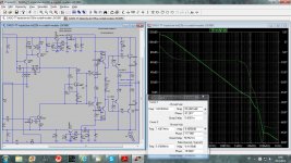
Here is first Loop Gain TMC simulation in “standard” way, TMC resistor is connected to the output and is not encompassed with the Middlebrook probe.
It shows first order slope as the Miller compensation.
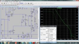
Second one is the same simulation, but TMC resistor is connected to the ground and that is now TPC(not optimized). It shows second order slope.
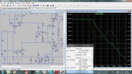
Third one is TMC simulation again but TMC resistor is not directly connected to the output but after the Middlebrook probe.
It shows second order slope similar to the TPC.
Bear in mind that all those simulations are of the Loop Gain(feedback) not Open Loop Gain.
Damir
Attachments
Hi Damir,Sorry I did not answer your question sooner, I was busy doing Spring works in my garden.
This simulations are of my working TT amp, stable and playing for more than a year now.
First how you do the simulation here http://www.diyaudio.com/forums/soli...lf-wants-your-opinions-62.html#post3454170(of what?) is wrong. You should not use 1F capacitors to shorten negative input to the ground together with Middlebrook probe.
thank you for the carefull reply.
[ Spring has started, too, in Germany. During Easter, we still had good skiing conditions in the secondary mountain nearby. Now, a lot of trees start to flourish at the same time. Really nice. ]
I totally agree to the first two plots. With the third, I still have a problem. Is it of any physical relevance?
Let's simplify the problem a bit. We have an amplifier with a global feedback loop from output to the inverting input. Additionally, there is a second feedback loop from the output to an "intermediate" inverting input, here via the TMC resistor. So, we see an inner feedback loop (via TMC) nested into the outer global loop.
The question is: how should one evaluate these nested loops? My understanding till now was, and please correct me if necessary, that first we have to ensure stability of the inner loop alone. This gives a sub-circuit with certain characteristics which we later use as building block in the second, outer, loop.
In order to evaluate the inner loop, one can place the loop probe between OUT and the TMC resistor. The important point is, however, that the signal from the probe does not additionally go via the main inverting input through the circuit. Thus, I proposed to simply short the inverting input to ground. As the probe is a voltage source and the amplifier output has low impedance, this will not change the result.
As I pointed out in the post for the TPC/TMC amplifier, the result is nice: the inner TMC loop on its own has really good stability margins. This agrees with your observation that the amplifier works flawlessly in reality.
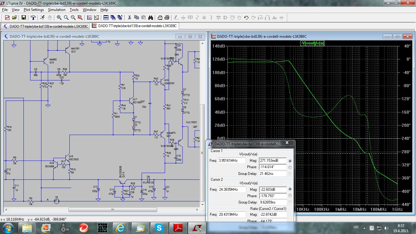
Back to the beginning: what is the physical meaning of your third Bode plot? If it really was an important NFB loop around the OPS, then I would run into serious trouble with my nested Miller compensation amplifier. In the picture below, I have simulated the loop behaviour equivalently to your third picture: the probe is placed between amplifier output and the connection of all feedback paths. The outcome would be that the unity gain crossover is about 1.2MHz with phase margin of 65 degrees, whereas in the evaluation in the thread on the nested Miller compensation, the result was about 400kHz / 85 degrees for each loop on its own. The same would hold for the breadboard amplifier that I have already built and that operates really properly just as yours.
Additionally, the steep slope of about 60dB per decade contradicts the smoth reaction of the amplifier on e.g. a square wave signal.
What do you think, Damir?
Is there anybody else who can comment on the issue?
Best regards,
Matze

Is there anybody else who can comment on the issue?
Hi Matze
Recently I have made a few posts about loop simulation that may help, in the Self thread.
I concur with Damir that the 1F short is not the best way to test.
It is error-prone and can alter the circuit impedances. There was a thread on this a while back where the poster had used this technique and so seriously altered the impedances as to produce rubbish. Your first example looked OK but I haven't checked your later use.
The V source that Damir uses is usually adequate but more robust is to use the Tian probe included as an example in LTspice.
Best wishes
David
BTW Matze is nickname, like Dadod for Damir, or Dave? For Mathias?
Last edited:
Hi Damir,
Hi David,
hopefully, we do not completely misunderstand. My point is merely the correct injection of probe signals, be it using the Middlebrook or Bob Cordell's approach. BTW, the latter is usually also my way because the amplifier output has quite low impedance.
I think we agree on the following two methods to evaluate the global NFB loop:


Nice stability margins in both cases, TMC produces first-order characteristics.
Now the "inner" loop due to TMC. As I still think, one should break the global loop in this case, here first again the method you are both questioning (shorted inverting input).

Next, two slightly changed methods without the brutal short. The second of both is again more comparable to Bob's approach.


In all cases, one sees comparable and nice results. Unity gain crossover about 450 kHz, phase margin around 90 degrees, gain margin more than 20 dB.
No surprise for me that the amplifier works that well. If being fussy, the only thing might be the slight "hump" above 10 MHz. In my eyes, it is an indication of a small problem somewhere in VAS or OPS.
[ The loop around the VAS has not yet been evaluated. ]
One question really has to be answered:
Does the loop that is probed above in the third picture http://www.diyaudio.com/forums/atta...355794-thermaltrak-tmc-amp-matze-tmc-lg-3.jpg have physical relevance?
Thank you both and Cheers,
Matze
Hi David,
hopefully, we do not completely misunderstand. My point is merely the correct injection of probe signals, be it using the Middlebrook or Bob Cordell's approach. BTW, the latter is usually also my way because the amplifier output has quite low impedance.
I think we agree on the following two methods to evaluate the global NFB loop:
Nice stability margins in both cases, TMC produces first-order characteristics.
Now the "inner" loop due to TMC. As I still think, one should break the global loop in this case, here first again the method you are both questioning (shorted inverting input).
Next, two slightly changed methods without the brutal short. The second of both is again more comparable to Bob's approach.
In all cases, one sees comparable and nice results. Unity gain crossover about 450 kHz, phase margin around 90 degrees, gain margin more than 20 dB.
No surprise for me that the amplifier works that well. If being fussy, the only thing might be the slight "hump" above 10 MHz. In my eyes, it is an indication of a small problem somewhere in VAS or OPS.
[ The loop around the VAS has not yet been evaluated. ]
One question really has to be answered:
Does the loop that is probed above in the third picture http://www.diyaudio.com/forums/atta...355794-thermaltrak-tmc-amp-matze-tmc-lg-3.jpg have physical relevance?
Thank you both and Cheers,
Matze
Yes, it stands for Matthias.BTW Matze is nickname, like Dadod for Damir, or Dave? For Mathias?
Hi Damir,
Hi David,
hopefully, we do not completely misunderstand. My point is merely the correct injection of probe signals, be it using the Middlebrook or Bob Cordell's approach. BTW, the latter is usually also my way because the amplifier output has quite low impedance.
I think we agree on the following two methods to evaluate the global NFB loop:
View attachment 343659
View attachment 343660
Nice stability margins in both cases, TMC produces first-order characteristics.
Now the "inner" loop due to TMC. As I still think, one should break the global loop in this case, here first again the method you are both questioning (shorted inverting input).
View attachment 343663
Next, two slightly changed methods without the brutal short. The second of both is again more comparable to Bob's approach.
View attachment 343661
View attachment 343662
In all cases, one sees comparable and nice results. Unity gain crossover about 450 kHz, phase margin around 90 degrees, gain margin more than 20 dB.
No surprise for me that the amplifier works that well. If being fussy, the only thing might be the slight "hump" above 10 MHz. In my eyes, it is an indication of a small problem somewhere in VAS or OPS.
[ The loop around the VAS has not yet been evaluated. ]
One question really has to be answered:
Does the loop that is probed above in the third picture http://www.diyaudio.com/forums/atta...355794-thermaltrak-tmc-amp-matze-tmc-lg-3.jpg have physical relevance?
Thank you both and Cheers,
Matze
Yes, it stands for Matthias.
Hi Matthias,
I am quite occupied with my garden now, but looking at your third picture I think it is not good enough. You disengage global feedback and look the "iner" loop trough TMC resistor only. Correct way, I think, should be looking for VAS local feedback loop. I tried it ones but was not satisfied with what I've got, it could not explain to me haw TMC decreases distortion at 20kHz(because TMC resistor connection at the output). Because that I used the method in my third picture and all TMC amps I built(yes there are some more in this thread) were stable and good sounding. Ones in the other forum(closed now) I've got positive answer requarding this method but never here.
When I get more free time I'll try to think of those simulation more, I think that you are on right track.
By the way my nickname is Dado not Dadod, I had to add d because this foumd did no accept dado.
BR Damir
Hi Damir,
I truly apologize for making you the trouble. The approach "first evaluate the inner (TMC) loop without outer global loop and than only have a look at the global loop" is wrong.
The reference jcx gave me in the thread on nested Miller compensation clearly shows how to transform intertwinned / nested loops into a form that only contains loops around single stages. (Boris Lurie: "Classical feedback control", chapter 2, Mason's rule)
In fact, as we cope with linear systems, the transformations are simple and perhaps really obvious.
Currently I'm working on an analysis of TMC that should allow to calculate analytically the loop gain you have simulated in a modell with idealized OPS / VAS / transconductance stages.
The bottom line is: in your amplifier as in mine, the ULGF around the output stage is quite high. Yours is around 4 MHz in your last version, in my breadboard amplifier with nested Miller compensation it is about 1.5 MHz instead of the targeted 300 kHz (5 times higher due to the 5 nested Miller loops). My approach additionally has the disadvantage that the NFB around the input stage is quite low. [ But the NFB around VAS/OPS is really giant. ]
Edit:
Additionally, each additional (not purely resistive) loop, be it TMC or "nested Miller", will really create higher-order behaviour somewhere in the system.
Best regards,
Matze
your approach to evaluate the total loop around the output stage is right, I was on the wrong track.When I get more free time I'll try to think of those simulation more, I think that you are on right track.
I truly apologize for making you the trouble. The approach "first evaluate the inner (TMC) loop without outer global loop and than only have a look at the global loop" is wrong.
The reference jcx gave me in the thread on nested Miller compensation clearly shows how to transform intertwinned / nested loops into a form that only contains loops around single stages. (Boris Lurie: "Classical feedback control", chapter 2, Mason's rule)
In fact, as we cope with linear systems, the transformations are simple and perhaps really obvious.
Currently I'm working on an analysis of TMC that should allow to calculate analytically the loop gain you have simulated in a modell with idealized OPS / VAS / transconductance stages.
The bottom line is: in your amplifier as in mine, the ULGF around the output stage is quite high. Yours is around 4 MHz in your last version, in my breadboard amplifier with nested Miller compensation it is about 1.5 MHz instead of the targeted 300 kHz (5 times higher due to the 5 nested Miller loops). My approach additionally has the disadvantage that the NFB around the input stage is quite low. [ But the NFB around VAS/OPS is really giant. ]
Edit:
Additionally, each additional (not purely resistive) loop, be it TMC or "nested Miller", will really create higher-order behaviour somewhere in the system.
Best regards,
Matze
Last edited:
- Status
- This old topic is closed. If you want to reopen this topic, contact a moderator using the "Report Post" button.
- Home
- Amplifiers
- Solid State
- ThermalTrak+TMC amp