Sanken transistors can be purchased from here, reliable dealer.
Pacific Semiconductors USA - Worldwide Distributor-Import-Export
Pacific Semiconductors USA - Worldwide Distributor-Import-Export
"as simple as possible, but not simpler".

Yes, the PCB that Ovidu did for their front end was too complicated for me to hope to equal, but a simpler circuit that is not too far away will make me happy.I am impresed with Stuart's amps and I learned a lot from him, but one thing keep me from implementation, to complicated PCB layout and I don't think I am qualified to develop good enough one. Still with simpler design you can get very close to his level of distortion, simulated only, but Stuart's amps were simulated only too.
Complementary symmetry front end is not important for me, I am more to D. Self reasoning.
What is Bob Cordell's resistor load, I bought his book but don't remember that?
dado
I know you are not a fan of the symmetrical front end and I think your reasons are sensible. For my particular application (compression drivers) I need very low noise so a lot of current in the LTP. That makes the bias current more of a problem. So a symmetrical circuit reduces the noise (as even Self admits) and cancels the bias currents too (as much as I make an effort to match Hfe of course).
Bob Cordell current mirror resistor load is on p139. He shows with simple Miller compensation but it can be better compensated I believe.
Best wishes
David
I will check how 1/f noise is modelled in SPICE, if at all. I don't recall I have seen it discussed.
Best wishes
David
Noise is modelled by just 2 parameters, AF (an exponent) and KF (the factor) so not too complicated.
And KF is normally defaulted to 0 so they not used anyway
The VBIC model in LTSPICE has an additional parameter for 1/F noise.
Best wishes
David
Last edited:
Thanks a lot Homemodder. Too bad they only have the non-graded version.
The 2SC3284 is better than the 2SC5200 and cheaper. Two parallel C3284 will take up the same space but be faster, handle more power, and be twice as linear as the MT-200 2SC2922. That is my reasoning anyways.
The 2SC3284 is better than the 2SC5200 and cheaper. Two parallel C3284 will take up the same space but be faster, handle more power, and be twice as linear as the MT-200 2SC2922. That is my reasoning anyways.
All the sankens will be graded, You should just contact them for the details. Its difficult finding dealers selling sankens I dont know why and there fakes everywhere, its terrible at ebay.
I see what you mean with parralelling, I frequently use 2 pairs of 2sa1186/2sc2837 for 100 w amps, these have excellent performance as well and more sellers.
I see what you mean with parralelling, I frequently use 2 pairs of 2sa1186/2sc2837 for 100 w amps, these have excellent performance as well and more sellers.
Profusion has the 2SC6145AY/A2223AY, these are even better, only a little slower than the C3284/A1303, and even cheaper! I decided to get them instead. They are still plenty faster than the C5200/A1943. I don't think high-current Ft matters, just the speed at the crossover region, the larger LAPT Sankens are actually worse in this regard. Low-current Ft is dominated by Cje or Cbe, so maximizing Ft at 100mA (meaning lowest Cbe) will get you better switching behavior. This is also one way the MT-100's are better than the MT-200's. High Ft at 3A is not necessarily a good thing, if your amp is compensated for the relatively low Ft in the crossover region.
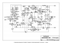
MK2
I replaced D4 LED with 10V zener, and now there is about 10V source-drain, better working point for LSK389. I could not hear any difference between previous version(3V source-drain) and this one. It did not increase noise, I put my ear close to the loudspeaker and heard nothing.
dado
I replaced D4 LED with 10V zener, and now there is about 10V source-drain, better working point for LSK389. I could not hear any difference between previous version(3V source-drain) and this one. It did not increase noise, I put my ear close to the loudspeaker and heard nothing.
dado
Attachments
this is not the usual way to define noise.It did not increase noise, I put my ear close to the loudspeaker and heard nothing.
this is not the usual way to define noise.
Of course not, I will measure it, but to compare with previous version is good enough. A pleasure wile listening is a goal.
")
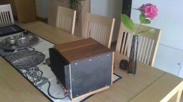
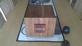
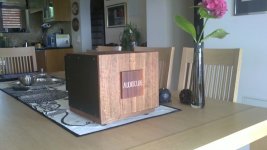
Finally AUDIOCUBE has it's wooden box.
Beautiful work of art!
this is not the usual way to define noise.
I did measure Signal to Noise with 8 ohm load:
Signal/noise = 109dB reference to 1 w output power.
I used my audio milivoltmeter with 1mV full scale and it barely muved and showed 10uV so it coud be that this result is not very accurate but good enough to show that this amp is very very quiet.
During this measurement I noticed some very small 2MHz oscilation(cca 0.5 mV pp, but only vith the load connected(that was not showed on the milivoltmeter as it works up to 100kHz). It looks that it is provoked by the feedback from the output wires passing over PCB. It not influences the sound(at least I coud not find any) but I intend to change internal loudspeaker wiring and use shielded one, but not sure what to use for that kind of the current.
dado
Twist the speaker wires. The flow and return must follow the same route for the whole route.
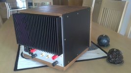
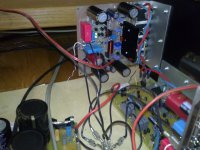
Yes I know that is important, I used a loudspeker cable for that. The problem is that the loudspekar PCB output is in some distantce from common power ground were the loudspeaker ground wire is connected and in that part the wires are separated. Attached photo shows that before I put the into the box but the loudspeaker connection is very similar.
dado
Attachments
I think the return route of the speaker cable must follow the trace route that the speaker output current follows and then continue on to the final connection at the star ground (Main Audio Ground) This would require the Return lead to follow the underside of the PCB to be as close as possible to the trace that carries the current.
Note that if this is not done both the flow current trace and the return current cable will both affect the low level circuits in their vicinity.
It will easier on some PCB layouts for this to be achieved. On some PCB layouts this "following" may be close to impossible. That would be a failing of the PCB designer to recognise that currents flow in loops and that the "loop area" of his traces will affect the performance of his PCB design.
Some years ago I referred to a Leach paper where he showed this PCB design, but at the time I could not find a web address for the paper.
Last edited:
I think the return route of the speaker cable must follow the trace route that the speaker output current follows and then continue on to the final connection at the star ground (Main Audio Ground) This would require the Return lead to follow the underside of the PCB to be as close as possible to the trace that carries the current.
Note that if this is not done both the flow current trace and the return current cable will both affect the low level circuits in their vicinity.
It will easier on some PCB layouts for this to be achieved. On some PCB layouts this "following" may be close to impossible. That would be a failing of the PCB designer to recognise that currents flow in loops and that the "loop area" of his traces will affect the performance of his PCB design.
Some years ago I referred to a Leach paper where he showed this PCB design, but at the time I could not find a web address for the paper.
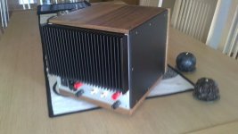
Thanks Andrew, what would you suggest how to route the loudspeaker wires with this PCB attached.
dado
Attachments
Hi Dadod,
Is there a PCB group buy for your amp?
No, there was no interest until now.
dado
- Status
- This old topic is closed. If you want to reopen this topic, contact a moderator using the "Report Post" button.
- Home
- Amplifiers
- Solid State
- ThermalTrak+TMC amp