Well, I think you would want to set the pole corner frequency low enough to ensure that the ULGF of the MIC loop occurred at 20 dB/ decade. You could TPC it I suppose, but my goodness why would you want to- just for a few more dB of loop gain?
Actually with TPC MIC you get significantly greater major loop gain than with ordinary MIC: some 20dB greater loop gain at 20KHz in fact.
Attachments
Hi Bob,
Your error corrected design of 1984 uses 20p for MIC. Given that you used degenerated JFETs for the input stage, producing significantly lower transadmittance gain than similarly degenerated BJTs, I suspect that the value of this capacitor could have been further reduced to, say, 10p. A value of 20p would have been just right, I suspect, if you had used BJTs for the input stage.
I am also a bit dubious about the utility of the 680 ohm (R13) in series with the MIC capacitor. The resistor adds a zero to the major loop gain response that is far beyond unity loop gain. The value of this resistor should have been in the region of 2.2K to bring the zero closer to unity loop gain frequency so as to enhance stability margins. Moreover if the zero is placed just before unity loop gain frequency, it has the effect of grossly extending the unity loop gain crossover, which may again compromise stability margins.
Additionally, care must be exercised as inclusion of R13 in series with the MIC capacitor compromises the MIC local loop's stability margins.
Your error corrected design of 1984 uses 20p for MIC. Given that you used degenerated JFETs for the input stage, producing significantly lower transadmittance gain than similarly degenerated BJTs, I suspect that the value of this capacitor could have been further reduced to, say, 10p.
A value of 20p would have been just right, I suspect, if you had used BJTs for the input stage.I am also a bit dubious about the utility of the 680 ohm (R13) in series with the MIC capacitor. The resistor adds a zero to the major loop gain response that is far beyond unity loop gain. The value of this resistor should have been in the region of 2.2K to bring the zero closer to unity loop gain frequency so as to enhance stability margins. Moreover if the zero is placed just before unity loop gain frequency, it has the effect of grossly extending the unity loop gain crossover, which may again compromise stability margins.
Additionally, care must be exercised as inclusion of R13 in series with the MIC capacitor compromises the MIC local loop's stability margins.
Last edited:
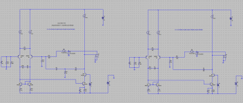
Bob, also note that only a fifth of the value of the compensation capacitor used with ordinary miller compensation may be used with MIC for the same loop gain. (do you know why this is the case?
Already answered unless post 699 is wrong, in which case I would also like the answer to this question. Component numbering in 699 refer to your schematics in 686.
Edit: I thought I'd add Ed Cherry's comments on MIC from his 1982 AES paper 'Feedback, Sensitivity and Stability of Audio Power Amplifiers'.
"[MIC] is very nearly equivalent to increasing C [the usual Miller capacitor] and of itself degrades sensitivity. However, if C is simultaneously reduced (or even removed), sensitivity can remain constant. This modification to Fig. 3 [the typical 3-stage amplifier topology] appears desirable, as it reduces the peak current demanded from the first stage and thereby reduces transient intermodulation distortion."
Last edited:
It's a function of the resistor values. For the usual Miller compensation, the ULGF is gm1*B/Cm. gm1 is the LTP transconductance; B is the feedback ratio which I have taken as approximately R7/R8? (can't read it) for closed loop gain >>1.
For the MIC, the ULGF is 1/(Cm*R14). R14 and R8 are the same resistor in the two circuits so can cancel out in the algebra.
For equal Cm in both cases, the result is 1/gm1 ~= R7. Since your 1/gm1 is about one-fifth of your R7, you need a 5x capacitor.
How did you arrive at the expression for ULGF for MIC?
I suspect MIC requires a capacitor one fifth the size of that for ordinary Miller compensation because the MIC loop encompasses more gain generating active devices in within the loop, as Wahab pointed out somewhere. I could be wrong though.
Note that J. L. Hood used excessively large capacitor values (~220p) for MIC in his amplifiers. This would have the effect of needlessley curtailing major loop gain, and probably explains why the linearity of his designs was mediocre.
Last edited:
I wonder if was not because his earlier designs used slow fT devices. With standard MC I suspect the ULGF would be 500kHz or thereabouts. Of course on his FET output designs, he could have gotten away with 2x to 4x that figure.
If I remember corrrectly, J. L. Hood used 220p MIC on his MOSFET designs. I am not certain he degenerated his input stage though.
Nevertheless, 220p is too high; should have been more like 22p methinks.
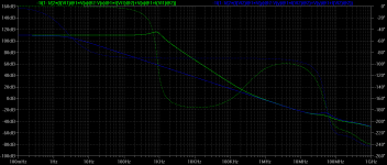
Actually with TPC MIC you get significantly greater major loop gain than with ordinary MIC: some 20dB greater loop gain at 20KHz in fact.
Yes, the TPC pole zero pair utilizes the available gain very effectively as you have shown.
How did you arrive at the expression for ULGF for MIC?
I suspect MIC requires a capacitor one fifth the size of that for ordinary Miller compensation because the MIC loop encompasses more gain generating active devices in within the loop, as Wahab pointed out somewhere...
Antonio provides evidence way back in this post that Steve is correct about the C and Rs time constant. This is a nice example of Rosenstark's method, that had previously seemed oddly random to me.
Best wishes
David
Last edited:
Antonio provides evidence way back inthis post that it is the C and Rs time constant that matters. This is a nice example of Rosenstark's method, that had previously seemed oddly random to me.
Best wishes
David
David's link is to post 664 for those who the link doesn't work for. You can see that he [edit: Magnoman/Antionio] made the usual Miller cap and the MIC cap the same value (100pF) by setting the feedback resistors appropriately.
To answer Mike K's question about how the ULGF for MIC is found, set the demanded gain (closed loop gain) of the MIC loop equal to the demanded gain of the global loop. Or look at the commentary to Fig 9.7 in Bob's book.
Last edited:
How did you arrive at the expression for ULGF for MIC?
I suspect MIC requires a capacitor one fifth the size of that for ordinary Miller compensation because the MIC loop encompasses more gain generating active devices in within the loop, as Wahab pointed out somewhere. I could be wrong though.
Note that J. L. Hood used excessively large capacitor values (~220p) for MIC in his amplifiers. This would have the effect of needlessley curtailing major loop gain, and probably explains why the linearity of his designs was mediocre.
Hi Mike,
Thanks for bringing to my attention that J.L. Hood had discussed MIC before I discussed it. Is there a publication reference for that? I'd like to get ahold of that so I can properly credit that in my next edition.
Cheers,
Bob
MIC does facilitate very high slew rates because the it=CV limit associated with standard Miller comp is broken - you no longer have the integrator. Indeed, slew rate performance then approaches or equals that of CFA's.
Exactly right, Bonsai.
Cheers,
Bob
Hi Mike,
Thanks for bringing to my attention that J.L. Hood had discussed MIC before I discussed it. Is there a publication reference for that? I'd like to get ahold of that so I can properly credit that in my next edition.
Cheers,
Bob
Ed Cherry also in 1982, although briefly (what I've quoted in post 723 is all of it AFAIR).
Ed Cherry also in 1982, although briefly
You have mail.
Best wishes
David
JLH & Slew rates.
I've just checked that he doesn't compensate his 1969 Class A amp at all. But he certainly discusses it in his 1975 HiFi News 75W amplifier series.
_______________
Bob I think it may be worth discussing the need for zillion V/us slew. A 100W@8R amp gives V = 40 exp(jwt) Volts at max power.
The slew rate for this is dV/dt = j w 40 exp(jwt)
If the amp has a first order roll-off at f3dB, then the maximum slew rate the amplifier needs is twice that for a rail to rail sinewave at f3dB. You get this for an unclipped square wave whose rise time will reflect the bandwidth of the amplifier.
Any other roll-off will require less slew rate until when you have a brickwall filter (eg Red Book CD) the requirement is the same as for a a rail to rail sinewave at f3dB.
This means that you'd only see zillion V/us slew when the amp is severely overloaded. Beyond a certainly level, the slew only reflects the linear bandwidth of the amp.
Overload recovery and the lack of nasty artifacts are usually more important than high slew when coming out of overload.
In fact, one could argue that slew rate should be deliberately limited to what's required for low THD on a rail to rail sinewave at 2 x f3dB. The harmonics on overload would be more 'benign' cos the result would be a truncated triangle wave instead of a square wave.
_____________________
On much surer psychoacoustic ground is deliberate bandwidth limiting. I don't think there is any need for a power amp to have a 3dB bandwidth exceeding 100kHz. Some parties, eg the Broadcast Organisations, in fact insist on much lower bandwidths.
ALL the reliable blind listening tests on band limiting of electronic signals, both this and the previous millenium, show a clear preference for the band limited signal from those who can reliably tell the difference.
Our 100W 8R, 100kHz amplifier only needs a slew rate of
2 x 40 x 2 x pi x 100,000 = 50.26 V/us
This is halved if its 3dB bandwidth is 50kHz and reduced by nearly 10x if it is only playing Red Book CD.
This has always been JLH's favourite method of compensation.Thanks for bringing to my attention that J.L. Hood had discussed MIC before I discussed it. Is there a publication reference for that? I'd like to get ahold of that so I can properly credit that in my next edition.
I've just checked that he doesn't compensate his 1969 Class A amp at all. But he certainly discusses it in his 1975 HiFi News 75W amplifier series.
_______________
Bob I think it may be worth discussing the need for zillion V/us slew. A 100W@8R amp gives V = 40 exp(jwt) Volts at max power.
The slew rate for this is dV/dt = j w 40 exp(jwt)
If the amp has a first order roll-off at f3dB, then the maximum slew rate the amplifier needs is twice that for a rail to rail sinewave at f3dB. You get this for an unclipped square wave whose rise time will reflect the bandwidth of the amplifier.
Any other roll-off will require less slew rate until when you have a brickwall filter (eg Red Book CD) the requirement is the same as for a a rail to rail sinewave at f3dB.
This means that you'd only see zillion V/us slew when the amp is severely overloaded. Beyond a certainly level, the slew only reflects the linear bandwidth of the amp.
Overload recovery and the lack of nasty artifacts are usually more important than high slew when coming out of overload.
In fact, one could argue that slew rate should be deliberately limited to what's required for low THD on a rail to rail sinewave at 2 x f3dB. The harmonics on overload would be more 'benign' cos the result would be a truncated triangle wave instead of a square wave.
_____________________
On much surer psychoacoustic ground is deliberate bandwidth limiting. I don't think there is any need for a power amp to have a 3dB bandwidth exceeding 100kHz. Some parties, eg the Broadcast Organisations, in fact insist on much lower bandwidths.
ALL the reliable blind listening tests on band limiting of electronic signals, both this and the previous millenium, show a clear preference for the band limited signal from those who can reliably tell the difference.
Our 100W 8R, 100kHz amplifier only needs a slew rate of
2 x 40 x 2 x pi x 100,000 = 50.26 V/us
This is halved if its 3dB bandwidth is 50kHz and reduced by nearly 10x if it is only playing Red Book CD.
If I remember corrrectly, J. L. Hood used 220p MIC on his MOSFET designs. I am not certain he degenerated his input stage though.
Nevertheless, 220p is too high; should have been more like 22p methinks.
JLH used 5pF in series with 470k resistor in his 80W MOSFET amp, but he used RC network too, C3, R3.
Damir
Attachments
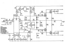
JLH used 5pF in series with 470k resistor in his 80W MOSFET amp, but he used RC network too, C3, R3.
Damir
Does it still work the same as MIC? With R10 > R14, the series impedance of the MIC compensation components is never <= the global feedback resistance.
I believe its still MIC, in sprit, if not in actuality. C6, along with Rdegen=5-- Ohms, R10 and C6 form the comp.
The LTP degen is pretty drastic, and this is why he got away with a high value for R10. I suspect the mosfet TIS transistor (Q10) gate capacitance also played a role here, but am open to correction on this one.
I think I would have done things a bit differently, but of course I have the benefit of a very good simmulator (LTSpice) and all the learning thats taken place the last 15 years or so in this field.
Thanks for bringing to my attention that J.L. Hood had discussed MIC before I discussed it.
Ed Cherry also in 1982, although briefly (what I've quoted in post 723 is all of it AFAIR).
The paper was written before March 1981.
What is curious is that Cherry calls it a "common" technique.
And thanks a "Dr R. R. Cordell" for a review of the paper
")
Best wishes
David
I believe its still MIC, in sprit, if not in actuality. C6, along with Rdegen=5-- Ohms, R10 and C6 form the comp.
The LTP degen is pretty drastic, and this is why he got away with a high value for R10. I suspect the mosfet TIS transistor (Q10) gate capacitance also played a role here, but am open to correction on this one.
I think I would have done things a bit differently, but of course I have the benefit of a very good simmulator (LTSpice) and all the learning thats taken place the last 15 years or so in this field.
Oh dear - I am going blind
- yes, those networks across the LTP mirror and the mirror ballast resistors. He must have had his reasons . . .- Status
- This old topic is closed. If you want to reopen this topic, contact a moderator using the "Report Post" button.
- Home
- Amplifiers
- Solid State
- Audio Power Amplifier Design book- Douglas Self wants your opinions