I use squeeging for an amplifier that has an impulse exited tail. Ringing is different in that the frequency of the wiggle is a constant. Resonance is ringing where the damping factor is less the .707. It has been so long since I have seen these distinctions I forget where they came from.
Now an amplifier that does any of the above is called "FWC."
ES
Now an amplifier that does any of the above is called "FWC."
ES
I'm getting close here Rick.
This is under the most non ideal conditions.
Crappy power supply, Boards sitting on my desk in open air no shielding. Board to board connecting wires far too long etc.
3Vrms @ 1Khz. SVO tuned with parallel Mdacs.
ARTA shows THD at 0.000024%
TT attenuation is 0.8dB for 2nd and 0.5db for all else.
This is under the most non ideal conditions.
Crappy power supply, Boards sitting on my desk in open air no shielding. Board to board connecting wires far too long etc.
3Vrms @ 1Khz. SVO tuned with parallel Mdacs.
ARTA shows THD at 0.000024%
TT attenuation is 0.8dB for 2nd and 0.5db for all else.
Attachments
Last edited:
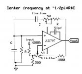
Repeated my measurements and here's the schematic (Ed the super-regen is sort of a joke for those that have tuned a tickler to the edge of oscillation).
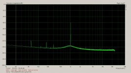
Dave, the noise floor is around -150dB as expected when I use no gain. Adobe Audition uses 2V rms as 0dB and the oscillator is running at 4.8V rms.
No gain in path, ref level is 2Vrms = 0dB, ocillator output is +7.6dB over this reference.
Readings are with passive twin-tee notch in path.
Fundamental (notched) 3960.205 -72.824836731
Second harmonic 7919.677 -130.707321167 corrected -129.3
Third harmonic 10880.859 -151.646469116 (noise)
Fourth harmonic 15840.087 -134.771347046 corrected ~-140
Fifth harmonic 19880.126 -152.193740845 (noise)
Attachments
Dick,
I know Scott is confused but you may be also.
.
Sorry Ed I'm not the least bit confused. I understand everything I am doing and why it does or does not work. If you can't keep up don't text and drive.
BTW - The caps I used were some brown ones out of the bin at work I think MPP, I did use a few ULT .01% resistors but also some from an eBay kit of lots of values. The board is a recycled rat-shack phenolic one. Thirds are almost at CLT level not bad.
Last edited:
Repeated my measurements and here's the schematic (Ed the super-regen is sort of a joke for those that have tuned a tickler to the edge of oscillation).
Dave, the noise floor is around -150dB as expected when I use no gain. Adobe Audition uses 2V rms as 0dB and the oscillator is running at 4.8V rms.
No gain in path, ref level is 2Vrms = 0dB, ocillator output is +7.6dB over this reference.
Readings are with passive twin-tee notch in path.
Fundamental (notched) 3960.205 -72.824836731
Second harmonic 7919.677 -130.707321167 corrected -129.3
Third harmonic 10880.859 -151.646469116 (noise)
Fourth harmonic 15840.087 -134.771347046 corrected ~-140
Fifth harmonic 19880.126 -152.193740845 (noise)
I'm good with -150dB.
Scott can you take another one of these and tune it to the 2nd on the output of the TT.
With bit less tickling it might pull up where the TT attenuated. Several tuned to the individual harmonics could give a nice flat response to measure by.
You could call it a harmonic tickler equalizer.
With bit less tickling it might pull up where the TT attenuated. Several tuned to the individual harmonics could give a nice flat response to measure by.
You could call it a harmonic tickler equalizer.
Last edited:
Repeated my measurements and here's the schematic (Ed the super-regen is sort of a joke for those that have tuned a tickler to the edge of oscillation).
Dave, the noise floor is around -150dB as expected when I use no gain. Adobe Audition uses 2V rms as 0dB and the oscillator is running at 4.8V rms.
No gain in path, ref level is 2Vrms = 0dB, ocillator output is +7.6dB over this reference.
Readings are with passive twin-tee notch in path.
Fundamental (notched) 3960.205 -72.824836731
Second harmonic 7919.677 -130.707321167 corrected -129.3
Third harmonic 10880.859 -151.646469116 (noise)
Fourth harmonic 15840.087 -134.771347046 corrected ~-140
Fifth harmonic 19880.126 -152.193740845 (noise)
I am sorry you are so confused you don't even know it.
")
Wow you mean I can drive now?
If I understand it then you have .000015% distortion. (Or did I double correct your correction?) Of course with a passive output filter you could halve this. Better passives might improve that a bit.
So what can you do with $50 worth of parts?
BTW your schematic is missing a dot.
Would you post the notch filter you are using and how it is loaded.
Thanks
ES
Last edited:
I am sorry you are so confused you don't even know it.
Wow you mean I can drive now?
If I understand it then you have .000015% distortion. (Or did I double correct your correction?) Of course with a passive output filter you could halve this. Better passives might improve that a bit.
So what can you do with $50 worth of parts?
BTW your schematic is missing a dot.
Would you post the notch filter you are using and how it is loaded.
Thanks
ES
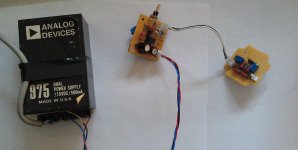
Standard twin-tee with trims that Jeff Smith and I published (you have to walk the trims to deep null). All frequency determining components are .033uF MPP and 1.26K Tiwanese 1%.
Like the picture?
Obviously there would be a benefit to a nice PC board in shielded enclosure, the line and light buzz does get through this setup. $50 you're killing me, $20 tops (less PS).
Attachments
Last edited:
Bob,
When you have what would be an oscillator without a level detector and gain adjust set just below oscillation you have a device that rings.
Scott refers to it as regeneration, but technically it is a resonator.
If you treat it as a black box and compare it to a tuning driven tuning fork, you would be hard pressed to see any difference.
ES
I doubt the mechanical linearity of a tuning fork would be -140dB. In fact the tuning fork rolls the frequency determining and compressive gain control all into one.
That very much depends on how you use it. If you use it as pure divider (one end driven from a low-Z source; other end grounded; no current flowing through the divider (i.e. facing a high-Z input)), its distortion contribution will be very small. I can't measure any distortion from an ordinary 10k cermet multi-turn trimmer in such an operating mode (harmonics near/below the measurement floor of about -130 dB, with 1 kHz/+16 dBu at the input of the trimmer), and with a wirewound part it would be even lower.
If you draw significant current through the wiper, the very nonlinear contact resistance will come into play. The magnitude is very variable, from type to type and from specimen to specimen. Also expect it to be a function of wiper position and probably also dependent on usage/wear. I have given some figures for cermet trimmers in this thread; probably a wirewound pot will be better, but expect no magic unless proven.
Certainly a fixed attenuator is the much more dependable means. Preferably you build it out of series connected equal value resistors, and make sure to keep the voltage across each to about 2 Vrms or less, and the power dissipation to 2 mW or less (that's for ordinary 1/4 W, 50 ppm metal film parts, and a distortion goal of < -140 dB).
Samuel
OK, great. thank you for your very well written response. My use of the WW pot draws insignificant (as in virtually nil) current through the wiper, so I should be good.
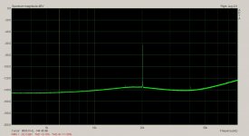
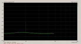
I'm getting close here Rick.
This is under the most non ideal conditions.
Crappy power supply, Boards sitting on my desk in open air no shielding. Board to board connecting wires far too long etc.
3Vrms @ 1Khz. SVO tuned with parallel Mdacs.
ARTA shows THD at 0.000024%
TT attenuation is 0.8dB for 2nd and 0.5db for all else.
Whoooa! Nice THD numbers.
Got more to do or are you ready to put up your schematic?
Thx-RNMarsh
Whoooa! Nice THD numbers.
Got more to do or are you ready to put up your schematic?
Thx-RNMarsh
Hi Rick,
I'm still working on the control of the SPI MDACs. The SPI transfer generates strong spurs in the audio band. This is not really much of a problem because data only needs to be sent when there is a frequency change. Otherwise the SPI is idle.
The bigger problem is when the USB is connected to the micro controller. The EMU0204 goes nuts. I don't know what EMU did to isolate from this. When I jump the EMU USB ground to the EMU analog input ground the EMU goes nuts as well. So this is a grounding problem with the EMU.
There is much work to be done and it will take a while to sort it all out.
I would like to submit a complete design rather than just bits and pieces.
So as Samuel said "be patient".
I do have the SPI transfer working properly now and with the fine tune on a 16 bit Mdac you can probably tune it right on a bin.
The range will have to be confined to 19Hz to 22kHz. The lamp multiplier simply doesn't have enough DR to operate in a range >22kHz. But it's distortion performance I think makes this forgivable.
I still need an output amplifier which can keep up and then there is a power supply to design as well.
After all this I need something to enclose it all in. It will have to be designed to fit something stock preferably.
After much work today I have this.
Attachments
USB shares ground with the PC host and it a real nightmare to isolate. There are isolators for USB 1.1 but not 2.0. The usual audio solution is I2S isolation(not easy). What I did in the QA400 isolator is to use the active differential stuff. The output chip is quite good http://www.ti.com/lit/ds/sbos094a/sbos094a.pdf . I don't know if its as good as the stuff we are discussing. You can easily do the same with discretes but the resistor matching is pretty critical. By referencing the output ground to the destination device the hum goes away. I am getting .0003% THD with the QA400 and the interface which is clearly the limits of the QA400.
Hi Rick,
The bigger problem is when the USB is connected to the micro controller. The EMU0204 goes nuts. I don't know what EMU did to isolate from this. When I jump the EMU USB ground to the EMU analog input ground the EMU goes nuts as well. So this is a grounding problem with the EMU.
I have the same problem with my scope and the EMU.
My EMU has two little knobs on bottom of the case for ground lifting.
They didn't seem to help when I tried them earlier. My other USB box (MOTU) has no problems and no ground lift switches but the drivers are no longer supported and it has different capabilities on each of my computers depending on age.
I have the same problem with my scope and the EMU.
I floated the ground on my scope. and thing are.....well much better.
- Home
- Design & Build
- Equipment & Tools
- Low-distortion Audio-range Oscillator