This might be of (historical) interest, though high Q was used more to increase frequency stability than to give low THD:
Tuning fork oscillators
You can use the same transducer for both sensing and powering, as in this device which surely won't have low THD, as a taut string has many easily-excited harmonic modes:
EBow - Wikipedia, the free encyclopedia
Tuning fork oscillators
You can use the same transducer for both sensing and powering, as in this device which surely won't have low THD, as a taut string has many easily-excited harmonic modes:
EBow - Wikipedia, the free encyclopedia
Two problems, odd harmonics only from a square wave and you also need phase adjustments for each harmonic. Easier to generate with the ADAU1701 DSP. $5.00 in 100's and can also be a crystal controlled frequency reference/injection source. I think this is the hard way but good technical pyrotechnics. .
In fact the same port used for injection lock would be very good for the harmonic cancellation input.
Is there a node in an SVO or Wein Bridge where the harmonics will be stronger than at the output, similar to the difference at the feed back input node?
In fact the same port used for injection lock would be very good for the harmonic cancellation input.
Is there a node in an SVO or Wein Bridge where the harmonics will be stronger than at the output, similar to the difference at the feed back input node?
Thanks David, you've just reminded me of all those Bulova watch ads from 40 years back!
Lol.
Two problems, odd harmonics only from a square wave and you also need phase adjustments for each harmonic. Easier to generate with the ADAU1701 DSP. $5.00 in 100's and can also be a crystal controlled frequency reference/injection source. I think this is the hard way but good technical pyrotechnics. .
In fact the same port used for injection lock would be very good for the harmonic cancellation input.
Is there a node in an SVO or Wein Bridge where the harmonics will be stronger than at the output, similar to the difference at the feed back input node?
There's two low pass filters in an SVO. So yes the harmonics will be stronger out of the BP output of an SVO where the slope is 6dB lower than the LP output. I haven't paid much attention to the harmonic levels from the HP output.
From what I've seen so far, I've deduced cancellation and compound are my choices for clean, effective and reasonably simple.
[btw - high Q BP harmonic selection has one more advantage in that the output is BP filtered of extraineous junk and noise to a large extent, built-in. Odds-only are no problem if you choose your fundamental correctly you get any harmonic freq desired... may just need 2 fund sq generator feqs. to cover odd and even freqs selected. Like 333Hz and 666Hz or what ever.]
Waiting for Samuel's circuit; Meanwhile..... more brainstorming.
Thx-RNMarsh
Last edited:
From what I've seen so far, I've deduced cancellation and compound are my choices for clean, effective and reasonably simple.
[btw - high Q BP harmonic selection has one more advantage in that the output is BP filtered of extraineous junk and noise to a large extent, built-in.]
Waiting for Samuel's circuit; Meanwhile..... more brainstorming.
Thx-RNMarsh
So what do you have in mind for compound. High current buffer and op amp or adding a gain stage in the loop?
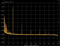
OK, tonights results. I set up my (for lack of a better word) regenerative amplifier at 4.2V rms as the 0 dB reference. I put the output through a twin-T filter after calibrating the gain through the path. There is probably a way to reduce the seconds a little more (-124dB after correction for the notch) but the rest all fall below -140dB or so. The distortion cap was added to the 797 which killed the thirds.
In the plot pictured remember the 2nds are 10dB more and the thirds 5 dB due to the notch being passive.
Schematic to follow. I used an EMU0204 and CoolEdit/Audition, one instance of Audition was doing the 3960Hz injection and I put it in the backround in an infinite loop. A second instance took the measurement in the forground.
The result was very stable and useful as a test source (IMNSHO).
EDIT - I think I will call it the Noscillator.
Attachments
Last edited:
How sensitive is it to the regen setting? If you turn that down and increase the drive does the distortion increase?
Seperate- how close to the residual distortion of the opamp is this? if you measure the opamp with the boosted noise gain do you get a similar spectrum of distortion (I'm thinking of a way to predict the ultimate performance of a system that is amplifier limited)
I found a nice little FFT analyzer program here free: ???????? ???????????? WaveSpectra ƒNƒ�ƒbƒN‚̃Wƒbƒ^�[‚Ì‘ª’è•û–@‚»‚Ì3
wavespectra, that seems to work pretty well. May be easier than Audacity for these tasks. It supports up to 384KHz sample rates (not that you can find much to capture with at that rate). Its also an interesting site that Google translates pretty well.
OK, tonights results. There is probably a way to reduce the seconds a little more (-124dB after correction for the notch) but the rest all fall below -140dB or so. The distortion cap was added to the 797 which killed the thirds.
In the plot pictured remember the 2nds are 10dB more and the thirds 5 dB due to the notch being passive.
The result was very stable and useful as a test source (IMNSHO).
EDIT - I think I will call it the Noscillator.
The SW-NO. Very cool. And the THD+N would be?? OR just the noise?
Thx-RNMarsh
OK, tonights results. I set up my (for lack of a better word) regenerative amplifier at 4.2V rms as the 0 dB reference. I put the output through a twin-T filter after calibrating the gain through the path. There is probably a way to reduce the seconds a little more (-124dB after correction for the notch) but the rest all fall below -140dB or so. The distortion cap was added to the 797 which killed the thirds.
In the plot pictured remember the 2nds are 10dB more and the thirds 5 dB due to the notch being passive.
Schematic to follow. I used an EMU0204 and CoolEdit/Audition, one instance of Audition was doing the 3960Hz injection and I put it in the backround in an infinite loop. A second instance took the measurement in the forground.
The result was very stable and useful as a test source (IMNSHO).
EDIT - I think I will call it the Noscillator.
How did you get the EMU noise floor down to -160dB?
Thanks David, you've just reminded me of all those Bulova watch ads from 40 years back!
My brother had one and could tune his guitar from it,
though the sound was quite high-ish.
I did not like the constant tone when trying to sleep, but
one probably gets used to it.
Gerhard
How did you get the EMU noise floor down to -160dB?
I'll double check my calibration process, I don't think I missed anything. Right now we are in police lockdown.
0 dB was arbitrarily scaled to 4.2V rms by me just to make the harmonics directly readable. We have our own waveform post processing software that I can use at home.
The FBI has ID'd the two guys responsible for Monday, they were from Cambridge apparently. They are back here now loking for one.
The FBI has ID'd the two guys responsible for Monday, they were from Cambridge apparently. They are back here now loking for one.
Last edited:
0 dB was arbitrarily scaled to 4.2V rms by me just to make the harmonics directly readable. We have our own waveform post processing software that I can use at home.
The FBI has ID'd the two guys responsible for Monday, they were from Cambridge apparently. They are back here now loking for one.
Oh. I can't do that with ARTA.
ARTA will only allow 1000mVrms max calibration so I have to attenuate higher levels to 1Vrms. This is how it's down in most analog Analyzers. The input is scaled to some FS value and maintained by a auto leveler. The EMU 0204 can't do more than what I show in my plots without rescaling the gain of the hardware.
Can you try normalizing yours this way and see what you get. I can't rap my head around what you've done.
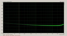
This is the EMU0204 with input shorted and 0dB set to FS of the ADC.
Your plot is 10dB better than this.
Attachments
Last edited:
Oh. I can't do that with ARTA.
ARTA will only allow 1000mVrms max calibration so I have to attenuate higher levels to 1Vrms. This is how it's down in most analog Analyzers. The input is scaled to some FS value and maintained by a auto leveler. The EMU 0204 can't do more than what I show in my plots without rescaling the gain of the hardware.
Can you try normalizing yours this way and see what you get. I can't rap my head around what you've done.
This is the EMU0204 with input shorted and 0dB set to FS of the ADC.
Your plot is 10dB better than this.
Sure, the EMU seems to use 2Vrms as full scale? One other problem I have to work around is getting the full duplex to work at 24bits.
How are you adjusting the output voltage? If you are using a variable resistor as a potentiometer that could have as much distortion as you are showing.
I consider the lockdown a good thing. There are a lot of law enforcement officers who have been up all night and are running on adrenaline. Good works or not "The nail that sticks up gets hammered down."
I consider the lockdown a good thing. There are a lot of law enforcement officers who have been up all night and are running on adrenaline. Good works or not "The nail that sticks up gets hammered down."
How are you adjusting the output voltage? If you are using a variable resistor as a potentiometer that could have as much distortion as you are showing.
I consider the lockdown a good thing. There are a lot of law enforcement officers who have been up all night and are running on adrenaline. Good works or not "The nail that sticks up gets hammered down."
It's before the filter.
How are you adjusting the output voltage? If you are using a variable resistor as a potentiometer that could have as much distortion as you are showing.
I consider the lockdown a good thing. There are a lot of law enforcement officers who have been up all night and are running on adrenaline. Good works or not "The nail that sticks up gets hammered down."
That is a pitfall of using a variable wire wound pot for attenuating.
I should put together a fixed resistor attenuator.
Last edited:
- Home
- Design & Build
- Equipment & Tools
- Low-distortion Audio-range Oscillator