Did that guy cut them for you?
HeatsinkUSA can get machine work done from a machine shop nearby at reasonable cost. Below I attached some pdf's of some drawings I sent to them for 2 monoblock F5T, using c'viller v2 boards, in case that will help anyone. The total cost was very reasonable. The holdup now is that I am trying to find an anodizer locally for a fair cost. The layout is similar to buzzforb's and looks like 2 large mono ACA's. I am using 6" heatsinks on the sides and polycarbonate for the top/bottom/back. The PS is a dual mono in a different chassis. I got the copper plate (for heat spreader) and angle steel (or aluminum) from Online Metal Store | Small Quantity Metal Orders | Metal Cutting, Sales & Shipping | Buy Steel, Aluminum, Copper, Brass, Stainless | Metal Product Guides at OnlineMetals.com. I am using mica under the FET's with Quantum heat sink compound from TIM-Consultants - Thermal Grease Specialists which is cheap and tied with the best from a test. I can email an interactive 3D view pdf (4.3meg, too big to attach) if anyone PM's me.
Attachments
Hi Sangram and 6L6
I followed your advice and here is what happened.
Left channel is ok. Right audio board, however the little FET J74 / Q2 smoked, so I quickly shut the power down. Waited a while to cool and then powered up again this time quickly turning pots to bring output voltage with no load from 7v to about 0.2v on the output. Then added input (2v from preamp) then my expensive speakers. Nothing! not even a buzz
I'm guessing now, I may have made a mistake by wiring the two grounds from input to R1 to ground between R3 and R4??
Any other tests I can do to enable me to sort this out and get some sound out?
Appreciate any good advice
F5 smoking FET
Hi 6L6
No worries about the J74, I could not find Toshiba ones so bought four Q J74 GR4C of 'Audio Wind, Ebay.
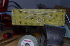
I have attached some photos which I hope make some sense. As I have used point to point wiring, shown photos from top and underneath for you. Hope they are clear enough?
Thanks for offering to help
Hi 6L6
No worries about the J74, I could not find Toshiba ones so bought four Q J74 GR4C of 'Audio Wind, Ebay.
I have attached some photos which I hope make some sense. As I have used point to point wiring, shown photos from top and underneath for you. Hope they are clear enough?
Thanks for offering to help
Attachments
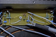
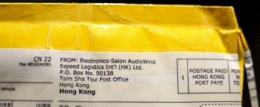
Fake J74 FET transistors from Electronics-Salon AudioWind
Hi Buzzforb
This is hard for me to accept given all the hours and cash invested, however it seems I have indeed been cheated by this Ebay seller 'AudioWind' who are based in Hong Kong. See photo of their address. A warning to all other potential F5 builders out there.
Bearing in mind Toshiba stopped making these in 2008 where do other builders source genuine parts from? Or are there quality alternatives?
Attachments
THe difficulty in helping with P2P board is our dependance on your finding the problem. No timplying anything. Since there is no standard layout to follow, tracing components and layout is very difficult. We cant really spot a problem, per se. I may have extra f5 board laying around. Let me see.
Thanks!
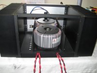
This was made to hold that heavy load of 25Kg in place - 11.0 Kg of heatsinks, 8Kg of transformers, 2Kg of parts and 4Kg of Aluminum plates. Below is image before metal partition sheet to be welded and only frame was ready. Its lightweight only 1.5Kg.
View attachment 339798
Hi Omishra, I only now see the pictures of your amp. That's some nice peace of work!
I'm going to study your pictures to see if I can have some smart construction details from you...
I have the same softstarts..only 9 euros on ebay
and they are doing exactly what they are suppose to do..Walter
Making some progress...
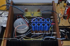
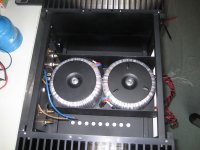
PSU is build and tested, it's modular, it can be removed as a whole from the amplifier.
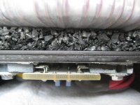
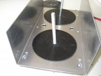
All the nasty and noisy rectifiers are shielded under the transformers...
ZM told me the rectifiers would be warm, so I made a U-profile for extra cooling and at the same time shielding for the large 625 VA transformers. Also the thick rubber is his idea...Yes I do listen sometimes
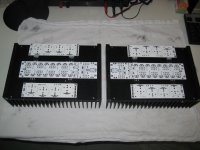
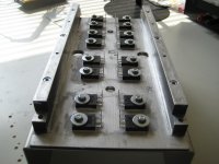
All PCB holes in the sinks are drilled and tapped. All transistor's are matched and selected, just like the resistors.
So now the nice part of populating the PCB's starts..."bestücken" yeah..
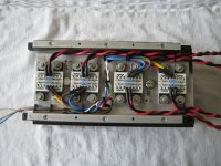
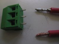
My last pic with the green terminalblock...what is better? Tinned leads, or just with the bare copper leads ???
What gives the lowest contact resistance? Also in long term?
Or should I not use them at all, and solder the leads directly on the PCB's?
But then my PSU is not so modular anymore
Walter
PSU is build and tested, it's modular, it can be removed as a whole from the amplifier.
All the nasty and noisy rectifiers are shielded under the transformers...
ZM told me the rectifiers would be warm
, so I made a U-profile for extra cooling and at the same time shielding for the large 625 VA transformers. Also the thick rubber is his idea...Yes I do listen sometimesAll PCB holes in the sinks are drilled and tapped. All transistor's are matched and selected, just like the resistors.
So now the nice part of populating the PCB's starts..."bestücken" yeah..
My last pic with the green terminalblock...what is better? Tinned leads, or just with the bare copper leads ???
What gives the lowest contact resistance? Also in long term?
Or should I not use them at all, and solder the leads directly on the PCB's?
But then my PSU is not so modular anymore
Walter
Attachments
-
 7.PCBs on sinks.jpg333.6 KB · Views: 321
 -
 6.PSU in case.jpg329.9 KB · Views: 307
 -
 5.modular PSU.jpg305 KB · Views: 409
 -
 4.rubber under transformers.jpg427.1 KB · Views: 436
 -
 3.PSU-bottom.jpg405.9 KB · Views: 438
 -
 2.rectifiers.jpg293.3 KB · Views: 442
 -
 1.transformer-shielding.jpg254.2 KB · Views: 459
 -
 8.what is better.jpg219.7 KB · Views: 289
Last edited:
So I got f5 turbo boards from the DIY Audio store and am collecting parts.
Since I missed the group buy for the fqa output fets I now have a decision to make. Use the irfp parts or the fqp parts. I am leaning towards the irfp9240/240 because they are bigger so they can dissipate heat better. Give me some opinions.
How many should I buy to get some decent matches? I will be using 2 pair per channel with 30 volt rails.
Thanks as always, Evan
So I got f5 turbo boards from the DIY Audio store and am collecting parts.
Since I missed the group buy for the fqa output fets I now have a decision to make. Use the irfp parts or the fqp parts. I am leaning towards the irfp9240/240 because they are bigger so they can dissipate heat better. Give me some opinions.
How many should I buy to get some decent matches? I will be using 2 pair per channel with 30 volt rails.
Thanks as always, Evan
Didnt miss anything
Wonderful job Walter.Making some progress...
PSU is build and tested, it's modular, it can be removed as a whole from the amplifier.
All the nasty and noisy rectifiers are shielded under the transformers...
ZM told me the rectifiers would be warm
All PCB holes in the sinks are drilled and tapped. All transistor's are matched and selected, just like the resistors.
So now the nice part of populating the PCB's starts..."bestücken" yeah..
My last pic with the green terminalblock...what is better? Tinned leads, or just with the bare copper leads ???
What gives the lowest contact resistance? Also in long term?
Or should I not use them at all, and solder the leads directly on the PCB's?
But then my PSU is not so modular anymore
Walter
Making some progress.........
ZM hate terminal blocks
saw too many crappy ones , in little service room , behind Iron Curtain

- Home
- Amplifiers
- Pass Labs
- F5 Turbo Builders Thread