I had used both direct heated and indirect types with the same wires returning only to heater winding scheme and they worked fine.
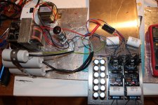
What I would do if in your shoes: I would put all the capacitors and resistors physically near one after another as your rectification & filtering schematic goes. Then I would connect the HV secondary winding center tap to first small value cap. I would return the (-) from each bigger cap there. I would not use big value output caps if there wasn't a choke after the first small cap. That is if I had to take it out to see if it saturates or picks stuff and put a resistor in its place.
What I would do if in your shoes: I would put all the capacitors and resistors physically near one after another as your rectification & filtering schematic goes. Then I would connect the HV secondary winding center tap to first small value cap. I would return the (-) from each bigger cap there. I would not use big value output caps if there wasn't a choke after the first small cap. That is if I had to take it out to see if it saturates or picks stuff and put a resistor in its place.
What ripple should I normally expect out of SSHVs?
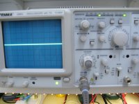
No ripple that you can see on a scope. Like what VGeorge posted in reply #1481 when loaded by the real preamp even.
"Last is on the output of SSHV2 on the anode choke, full BW and gain with 10X probes on my 20 MHz scope. "
Attachments
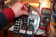
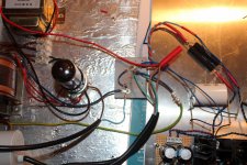
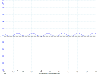
 I rewired all C-L-C, kept last dual R-C and ripple went down to around 24 mV (85 b4). I used 8 uF motor as first, dual 50 uF motors (470 lyt b4) at second.
All grounding, first, second and third is on same star.
What now? Maybe change last dual C (the rows of 33 uF 450 v). Sand rectifiers. I'm out of ideas

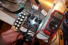
Shorten the wiring loops to minimal. Get the resistors very near to their caps that create the RC cell with. Make sure that your choke isn't saturating at the constant current that your SSHV2's are set for when combined. Its the ground, use best point that gives you min mV. The loop area is enormous, the Tx field is near. Minimize minimize minimize.
If the ripple in is in the order of mV, the problem has to be with the regulator, or with the way you measure it. If I were you I'd just use the regulator with the circuit it's for. If it's quiet, enjoy it and measure it when you get a better scope. If it's not quiet, pull it out and start debug the regulator.
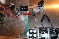
I am suspicious of the bank of caps wiring situation. It returns through the CCS input connectors.
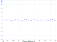
I am to. Heres a shot: 499 mS peak to second lowm 85 mV P-P
- Home
- Amplifiers
- Tubes / Valves
- 6V6 line preamp