Looking good Tony ")
I'd be really interested to know how you plan on drilling your top.
I have a router and I have a jig in mind, but perhaps there is an easier way
On my stuff, I have just received the 0.012uF FT3 Russian teflon cap for C8.
I did not have time to try it since I have been playing with interconnects today, but I will try it tomorrow.
Here is a photo for relative size reference (It s the left ones).

Jarek the wrapped one is yours Incoming soon.
I'd be really interested to know how you plan on drilling your top.
I have a router and I have a jig in mind, but perhaps there is an easier way
On my stuff, I have just received the 0.012uF FT3 Russian teflon cap for C8.
I did not have time to try it since I have been playing with interconnects today, but I will try it tomorrow.
Here is a photo for relative size reference (It s the left ones).
Jarek the wrapped one is yours
Incoming soon.I'd be really interested to know how you plan on drilling your top.
I have a router and I have a jig in mind, but perhaps there is an easier way
Thanks. I was staring at my Dremel tool and it struck me that they probably make a "spiral" bit for cutting through thin laminates. Sure enough they do. It's part of accessory #565, which I bought at my local home store. Since the top is a 1/4" thick hardwood sheathed ply I figure that's pretty close to a laminate. I'm going to try and use that to cut the outer dimensions. An L-square clamped to the panel material should insure a straight cut. I already know a spade bit will take care of the circular cutout needed for the TT platform. The slot for the laser head I'm still thinking about.
You can see I put 3/8" square stock along the inner perimeter. The top panel will have holes drilled through for #4 wood screws which will go into the square stock. The problem going this route is that the top will not be fastened in a way that will allow for frequent removal and reassembly. Those small screws will only going out and back into that wood so many times.
Looking forward to a report on those caps.
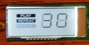
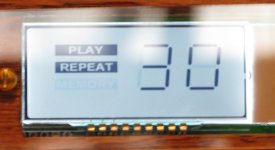
Is anyone else noticing a very narrow "angle of acceptance" for the display? I've been noticing that the viewing angle for proper visibility of the segments is very small. Any deviation from pretty much dead on center and the number segments tend to "shadow out" so it becomes hard to know whether they are on or off.
I thought Tibi said that was only for the earlier runs. He told me mine were both from the later run where the mod had already been incorporated. Tibi?
Yes, Tibi is here !
Your board is already modified and as far I remember a pot to adjust backlight is in place. The display, due his construction and LCD type, have a +/-45deg viewing angle with reference to central axis.
Regards,
Tibi
... what should I do?
Try turning the pot, dummy!

Yes, my board has the design update for the contrast control. I ran the pot through its range and found the best contrast level (for me). But the problem isn't really the contrast. It's that when you look straight on - dead on - at the display it looks like the segments which shouldn't be energized are slightly energized. If I lower my head so that I'm looking up at the display at about a 10 degree angle the display looks perfect. In the other direction, if I raise my eye level so that I'm looking down at the display by about 10 degrees I can't make out the energized segments from the unenergized - they all look "lit". No matter where I turn the pot while looking dead on at the display, I can't get the same clean image as when I look at it from slightly below.
Take a look at the pics. Actually, the straight on picture looks better than when I look at it in real life. Via eyeball the unlit segments are much more visible.
Attachments
an optical filter may help
Well, maybe, but I'd like to hope Tibi didn't intend for people to go out and search for optical filters.
I think you need to check for a tiny solder sliver somewhere!
Not quite sure I understand.
Well, maybe, but I'd like to hope Tibi didn't intend for people to go out and search for optical filters.
The display was adjusted for the source I sent to you. If you have used separate power supply, than the LCD bias was changed. I suggest you to power the LCD from a separate PS, trough a 5K-10K potentiometer.
A linear multiturn is recommended.
As the LCD is multiplexed, you need to adjust LC78601 pin 40 potential trough pot cursor.
One pot leg at +5V one at GND and middle (cursor) to LC78601 pin 40.
LCD working voltage is 4.8V. Try to get around this potential.
This will allow you to adjust contrast as you like.
Regards,
Tibi
The display was adjusted for the source I sent to you. If you have used separate power supply, than the LCD bias was changed.
Tibi, I'm using all of the supplied components for this Shiga. Power supply, LCD assembly, main PCB... all as supplied in the kit.
I have just changed the cap in C8 with a 0,012uF FT1 (had a 0,1uF FT3)
The first impression is that the sound is much more focused and clear but feels much less 3d. It also sounds like having much less... Don t know how to say this ... Like less grandeur...
Especially evident in sounds like tom drums or bitey guitar riffs. Attack power also seems less powerful. Sounds are less aggressive.
I will leave it like this for a few days so that the fresh cap breaks in a bit before I make a final decision
No it was not stock. It was an FT3 0.1uF. Going from stock to the ft3 made a huge difference
I have also just replaced the mur860s with msr860 (in the 8v reg), used one 2200uF panasonic FR replacing the two 1000uF I had before the 7808 and finally replaced the kit 7808 with one from On semi
The result was mostly obvious in textures and 3d spacial sounds. Metal cymbals sound a bit more natural also and bass notes have a bit more metal vibration in them. My test cd for today was the division bell from pink floyd
Not something to write home about, but still a quite positive change
I finally got the major cutouts done on the top cover. Took me all afternoon but after careful cutting and filing it fits almost perfectly. I have one or two small gouges I have to fix before final sanding and staining, and then this one will be done. 
Still not sure what to do about the display.
Still not sure what to do about the display.
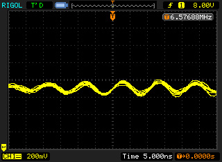
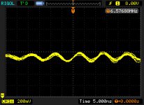
By the way, has anyone checked his 8V reg on a scope with just the 1000uF and 2200uF caps?
I just checked mine and it seems to have a ~200mV oscillation at around 6,5MHz
I had no sonic problems with my shiga, but still, would it be a nice idea to use 0.1uF caps to defeat that oscillation? Or it just does not matter for that kind of circuits?
BTW, the image does not change while playing cd
Attachments
- Home
- Source & Line
- Digital Source
- Finally, an affordable CD Transport: the Shigaclone story