Um, Ed. You can't get a guaranteed number for that.
Remember, it's not the bulk washer thermal resistance which is used, that would be it's conductivity and the total area. The thermal resistance of any washer will be dependent upon the heat spread above it in the package. a case with a bottom thickness of 40 mils will run hotter than a case with bottom thickness of 100 mils.
To get a rough idea of what it will be, you take the die size, add twice the package bottom thickness, then use that area for a thermal resistance calculation.
If the die is .250, like a IR450, a case bottom of .040 give an effective thermal area of .330 by .330.
If the case bottom is 100 mils, the effective area is .450 by .450, an area increase of 85%, and a thermal resistance decrease of 45%.
If you can't tell them what the effective area is to use in the thermal resistance calculation, then you can't expect them to give you a thermal resistance.
jn
I was aware of the limitations. But even using the concept of linear thermal resistance is wrong.
SY,
You know the one about the 45 year old lawyer who dies and goes to his eternal reward. He is greeted with "My oh my we have been waiting for you for so long...) To which he replies " I am only 45 years old!" And the punch line is?
SY and JN, I don't appreciate being criticized about what I know about semiconductor temp. ratings.
I have not criticised you for what you know.
I did however, criticize you for what you didn't know. It is clear you know very little about thermal transfer characteristics from the silicon to the sink. That is why I quoted you, and detailed the correct information.
so maybe I sort of know what I am doing, and I KNOW, as I have known for the last 45 years, how to derate a power transistor and estimate the internal chip temperature.
What you have posted contradicts that.
You're probably one of those guys who actually believes the derating curve in the manu literature is correct, and that it is a straight line...news flash, it ain't.
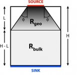
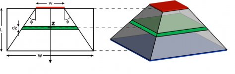
Remember I had to detail the 45 degree spreader model to you a decade ago over at AA??? Your knowledge at that time was rather, shall we say, wanting?.
I would be interested, however, in your suggestions as to how to get the rated power (or something close) from a T0-220,1/4 in(sq) device compared to a T0-3,1 in(sq) or equivalent package? Now here is where I could use your expertise!
It's not the package size, John...it's the die and spreading cone to the thermal interface. Sheesh, ten years...I woulda thought you'd have learned it by now.
Think of the breakthroughs that you can make with surface mount with your added expertise!
Did that 30 years ago John. You want expertise, just ask jacco about that aluminum oxide substrate bonded to the heatsink...that is expertise..
What sort of isolation pad that you would recommend? Al oxide, thermally conductive 'plastic' or BeO? Would you heatsink to copper, silver or diamond, or would aluminum do? Would you use a copper heat spreader as an interface between an aluminum heatsink and the device? So many questions. '-)
I gave you the information a decade ago. Now, google 45 degree heat spreader model. If you have actual, specific questions, just ask.
And remember, I told you ten years ago, if the thermal interface is significantly worse than the layers above, you can consider the upper surface isothermal.
jn
Last edited:
Ed, this way I am tuning my preamps and power amplifiers for minimum HF content at their outputs. Caps from RCA-jack grounds to chassis, types of cables used, grounding schemes, and stuff like this. One can reduce occurrence of HF spikes at more than 20dB. This is, IMO, almost most important for "good sound". Even milled case from a single block of Aluminum may not help, if all other good practices of HF rejection and HF input along cables rejection inside the box are permanently overlooked. One good example of overlooking of HF design principles is at the beginning of part I of this thread, with photo attached.
Pavel,
This is almost embarrassing, talking about real audio engineering, instead of fighting with J.C.
One of the interesting results was the effectiveness of the inter-winding Faraday shield. even though it is clear the inductance through the grounding system should limit the effectiveness at even moderately high frequencies (1 Mhz typical) the shield doesn't really ever drop below 6 db.
So your practical method of maintaining shield integrity (Same level surrounding all the parts) does (As any RF designer knows) work well.
There is another approach that is used in high RF environments. That is to use the feedback in a system to roll off the response above the band of interest but below the RF energy. This requires that the active circuitry still has gain at the RF frequencies.
Now lets see how many of the peanut gallery will give us their opinion as to why out of band noise is not important!
ES
No, it is not. Well, at least from between 1.8 K and 600 K.I was aware of the limitations. But even using the concept of linear thermal resistance is wrong.
Above 600K I've no experience (other than transient events of course.)

jn
Now lets see how many of the peanut gallery will give us their opinion as to why out of band noise is not important!
It depends on where it is in the circuit, doesn't it?
Tell me again, JN, or forever hold your criticisms of my 'limitations' '-)
Tell you what? About the 45 degree model? Oh for goodness sake, stop being so lazy...google 45 degree spreader model..
And do some reading..
[1] Kawka P. Thermal impedance measurements and dynamic modelling
of electronic packages. PhD thesis, University of Ghent, Belgium,
2005.
[2] Christiaens F, Vandevelde B, Beyne E, et al. A generic methodology
for deriving compact dynamic thermal models, applied to the PSGA
package. IEEE Trans Compon Pack Manuf Technol Part A 1998;
21(4):565–76.
[3] De Mey G, Vermeersch B, Kawka P. Thermal characterization of
electronic packages using the Nyquist plot of the thermal impedance.
In: 1st European advanced technology workshop on micropackaging
and thermal management, La Rochelle, France, 2006. Technical
presentations CD-ROM.
[4] De Mey G, Vermeersch B, Kawka P. Thermal impedance simulations
of electronic packages. In: Napieralski A, editor. Proceedings
of the 12th international conference on mixed design and integrated
circuits and systems (MIXDES 2005), Krakow, Poland, 2005.
p. 267–9.
[5] Vermeersch B, De Mey G. Thermal impedance plots of micro-scaled
devices. Microelectron Reliab 2006;46(1):174–7.
[6] Sze´kely V. Identification of RC networks by deconvolution: chances
and limits. IEEE Trans Circuits Syst I—Regul Pap 1998;45(3):
244–58.
[7] Sze´kely V, Van Bien T. Fine structure of heat flow path in
semiconductor devices: a measurement and identification method.
Solid-State Electron 1988;31(9):1363–8.
[8] De Mey G. Various applications of the boundary element
method. Oradea: University of Oradea (Romania); 2002. p. 61–2.
[9] Vermeersch B. Thermische diffusie in sinusregime (in Dutch). Master
thesis, University of Ghent, Belgium, 2005.
[10] Guenin BM. The 45_ heat spreading angle—an urban legend?
Electron Cooling 2003;9(4):10–2.
[11] David RF. Computerized thermal analysis of hybrid circuits. IEEE
Trans Parts, Hybr Packag 1977;13(3):283–90.
[12] Zimmer CR. Computer simulation of hybrid integrated circuits
including combined electrical and thermal effects. In: Proc of third
European hybrid microelectronics conference, Avignon, France,
1981. p. 44–50.
[13] Dean DJ. Thermal design of electronic circuit boards and packages.
Ayr: Electrochemical Publications; 1985. p. 75–90.
[14] Dobbelaere W, Matthys L, De Baetselier E, Goedertier W, De Mey
G. Heat spreading angles in multilayer structures. In: Proc 3rd
advanced training course mixed design of integrated circuits and
systems (MIXDES96), Lodz, Poland, 1996. p. 238–43.
[15] Masana FN. A closed form solution of junction to substrate thermal
resistance in semiconductor chips. IEEE Trans Compon Packag
Manuf Technol A 1996;19(4):539–45.
And that's from one hit..
And btw, a device submerged in a freon bath cools only by convection. Convection is subject to the viscosity, the temperature density dependence, and the geometry/orientation of the device.
jn
Attachments
Last edited:
No, it is not. Well, at least from between 1.8 K and 600 K.
Above 600K I've no experience (other than transient events of course.)
jn
And down below you discuss convection vs radiation? (Er now a bit above!)
The nice bit about the simple linear thermal model method is that if you get it a bit wrong, the extra heat is not as bad as predicted.
And down below you discuss convection vs radiation? (Er now a bit above!)
The nice bit about the simple linear thermal model method is that if you get it a bit wrong, the extra heat is not as bad as predicted.
You are confused on several points.
Power devices which are mounted to heatsinks are rated by conduction.
That is what the discussion has been.
John implied that immersion in freon was in some way good thermally, so I mentioned why it wasn't.
Radiation?? Where are you getting that from?? Nobody's mentioned that, especially me.
jn
Nice list of references.Tell you what? About the 45 degree model? Oh for goodness sake, stop being so lazy...google 45 degree spreader model..
And do some reading..
[1] Kawka P. Thermal impedance measurements and dynamic modelling
of electronic packages. PhD thesis, University of Ghent, Belgium,
2005.
[2] Christiaens F, Vandevelde B, Beyne E, et al. A generic methodology
for deriving compact dynamic thermal models, applied to the PSGA
package. IEEE Trans Compon Pack Manuf Technol Part A 1998;
21(4):565–76.
[3] De Mey G, Vermeersch B, Kawka P. Thermal characterization of
electronic packages using the Nyquist plot of the thermal impedance.
In: 1st European advanced technology workshop on micropackaging
and thermal management, La Rochelle, France, 2006. Technical
presentations CD-ROM.
[4] De Mey G, Vermeersch B, Kawka P. Thermal impedance simulations
of electronic packages. In: Napieralski A, editor. Proceedings
of the 12th international conference on mixed design and integrated
circuits and systems (MIXDES 2005), Krakow, Poland, 2005.
p. 267–9.
[5] Vermeersch B, De Mey G. Thermal impedance plots of micro-scaled
devices. Microelectron Reliab 2006;46(1):174–7.
[6] Sze´kely V. Identification of RC networks by deconvolution: chances
and limits. IEEE Trans Circuits Syst I—Regul Pap 1998;45(3):
244–58.
[7] Sze´kely V, Van Bien T. Fine structure of heat flow path in
semiconductor devices: a measurement and identification method.
Solid-State Electron 1988;31(9):1363–8.
[8] De Mey G. Various applications of the boundary element
method. Oradea: University of Oradea (Romania); 2002. p. 61–2.
[9] Vermeersch B. Thermische diffusie in sinusregime (in Dutch). Master
thesis, University of Ghent, Belgium, 2005.
[10] Guenin BM. The 45_ heat spreading angle—an urban legend?
Electron Cooling 2003;9(4):10–2.
[11] David RF. Computerized thermal analysis of hybrid circuits. IEEE
Trans Parts, Hybr Packag 1977;13(3):283–90.
[12] Zimmer CR. Computer simulation of hybrid integrated circuits
including combined electrical and thermal effects. In: Proc of third
European hybrid microelectronics conference, Avignon, France,
1981. p. 44–50.
[13] Dean DJ. Thermal design of electronic circuit boards and packages.
Ayr: Electrochemical Publications; 1985. p. 75–90.
[14] Dobbelaere W, Matthys L, De Baetselier E, Goedertier W, De Mey
G. Heat spreading angles in multilayer structures. In: Proc 3rd
advanced training course mixed design of integrated circuits and
systems (MIXDES96), Lodz, Poland, 1996. p. 238–43.
[15] Masana FN. A closed form solution of junction to substrate thermal
resistance in semiconductor chips. IEEE Trans Compon Packag
Manuf Technol A 1996;19(4):539–45.
And that's from one hit..
And btw, a device submerged in a freon bath cools only by convection. Convection is subject to the viscosity, the temperature density dependence, and the geometry/orientation of the device.
jn
Another remark: according to Bruce Hofer, he was deeply skeptical of how well a switching supply would work in the new lines of analyzers. I asked him about it after a presentation to the local AES chapter, and he was candid and forthcoming. Besides working for some time to locate a reliable vendor, and paying a good deal over typical prices for the same nominal performance, the key was to source a very good common-mode choke so the instrument would effectively be isolated from the mains.
Again according to Hofer, the benefits of the switchers include, finally and for the first time, no detectable line-frequency-related spurs in the DFT. Although some aspects of the new instruments, according to some friends' evaluations, are not quite as good as the system two, the removal of the toroid and its inevitable magnetic field radiation apparently accounts for the absence of the spurs.
Again according to Hofer, the benefits of the switchers include, finally and for the first time, no detectable line-frequency-related spurs in the DFT. Although some aspects of the new instruments, according to some friends' evaluations, are not quite as good as the system two, the removal of the toroid and its inevitable magnetic field radiation apparently accounts for the absence of the spurs.
You are confused on several points.
Power devices which are mounted to heatsinks are rated by conduction.
That is what the discussion has been.
John implied that immersion in freon was in some way good thermally, so I mentioned why it wasn't.
Radiation?? Where are you getting that from?? Nobody's mentioned that, especially me.
jn
I build my own heatsinks. They are part of the thermal circuit. There really is a reason to have them black anodized. I just am not enough of a DIYer to make my own air.
Another remark:
Again according to Hofer, the benefits of the switchers include, finally and for the first time, no detectable line-frequency-related spurs in the DFT. Although some aspects of the new instruments, according to some friends' evaluations, are not quite as good as the system two, the removal of the toroid and its inevitable magnetic field radiation apparently accounts for the absence of the spurs.
One of the big challenges with switchers is the changing frequency or duration to get the regulation. This generates subharmonics that can cause problems. Good common mode chokes that work to RF and up plus good magnetic isolation would be critical for success. Also capacitive coupling between input and output of the supply could compromise all the other work.
And then no audiophile worth his power cable fetish would let an evil switcher into his system.
I am repeating a point I made earlier- a really good, available switcher for low level stuff (25W-50W) would be really interesting.
trouble and confusion
Mr Curl,
mea culpa, I enjoy teasing you (and everyone else).
TO-3's went from small, medium, to oversize.
Then a smart guy at Fujitsu figured he could retain the two TO-3 mounting holes, but skip the base/emitter pins in the center.
Saves costs, and more versatile parts, you've been using the package type for quite a while in your power amp designs.
The British 120MHz SOT-223 devices may not be up to the task of delivering the power spec levels you commonly prefer.
But what's stopping them to entend the leadframe of an MT200 on the top, skip the center collector lead, plus the two mounting holes in the epoxy, somewhere in the future ?
For high-speed superyachts, the bottleneck is weight.
For power devices, the constraints are the interface, plus the package size.
Last edited:
That was the reference list from the first google hit in my search. The pics were also from that paper. I copied it only because I suspect the paper was not available to the general public, but available only to subscribers.Nice list of references.
My personal hardcopy papers were from the late 80's when I was in the military power hybrid business, but I don't have e copies of them.
jn
Of course they are. But you didn't ask any question about convection, fans, radiation, anodizing, nuttin. You made a statement about greased washers and the manu's refusal (so to speak), to give you numbers. I explained why they cannot.I build my own heatsinks. They are part of the thermal circuit.
Of course there is. Black heatsinks look really really cool..There really is a reason to have them black anodized.
jn
One of the big challenges with switchers is the changing frequency or duration to get the regulation. This generates subharmonics that can cause problems. Good common mode chokes that work to RF and up plus good magnetic isolation would be critical for success. Also capacitive coupling between input and output of the supply could compromise all the other work.
And then no audiophile worth his power cable fetish would let an evil switcher into his system.
I am repeating a point I made earlier- a really good, available switcher for low level stuff (25W-50W) would be really interesting.
Yes, heartily agree.
One of the challenges using small switchers, which are gradually becoming mandatory thanks to the efforts of ostensibly-benevolent energy conservation folk, is that the isolation from the mains is appreciably worse than lossy dual-bobbin transformers, both for conducted noise into and from. When the transformer looked like a few tens of picofarads the input reference, and in some cases the output, of the powered device constituted the dominant reference. And the transformer could be located at some remove from things, and with the dominant radiation falling off as the cube of distance the B fields could be appreciable but have little effect on circuitry.
But for switchers the tradeoff is isolation versus efficiency, so despite the higher operating frequency the capacitative coupling in the transformer is frequently worse. There are also explicit leakage parts included for compliance with various requirements that make things still worse. A lot of powered speakers that had done well with transformer wall warts failed badly when the supposedly-equivalent switcher was deployed.
The low-medium power switcher optimized for conducted and radiated noise and with exemplary regulation and output noise would indeed be interesting. By the way in conversation with Hofer he said they had a few millivolts of output noise on their new supplies (I was interested in this because someone in another forum insisted that switchers were now in the few-microvolt range, and I strenuously disbelieved that claim).
Another design chore that I suspect has yet to be executed optimally is a two-quadrant-output switcher for dealing with non-bridged class D amplifiers and their rail pumping. I am probably behind the times, but what I've seen so far are just ones which are able to tolerate their larger-than-typical output capacitors without seeing them as a short circuit when the power is cycled, or when recovering from a real short. Ideally one would return the energy all the way back to the mains.
Sorry, I was a bit wide reaching with my remark further back, modern SMD packages are designed to be very thermally efficient. Combined with layout techniques, the wealth of thermally engineered PCBs (metal clad etc) and active heat removal using phase change technology (heat pipes, just trying to sound technical) etc etc its amazing what can be achieved these days. A lot is down to the increasing demand for LED lighting, but also the density of modern designs require thermal management and considerations at the design stage. You can also get ceramic heatsinks with the copper pattern on the heatsink, almost the perfect thermal interface for the devices, layout has to be simple single sided.
Oh a thermal camera and black electrical tape can help the design cycle a lot, especially the black electrical tape
Using Thermal Calculation Tools for Analog Components Analog & Mixed-Signal slua566 - TI.com
, just trying to sound technical) etc etc its amazing what can be achieved these days. A lot is down to the increasing demand for LED lighting, but also the density of modern designs require thermal management and considerations at the design stage. You can also get ceramic heatsinks with the copper pattern on the heatsink, almost the perfect thermal interface for the devices, layout has to be simple single sided.Oh a thermal camera and black electrical tape can help the design cycle a lot, especially the black electrical tape
Using Thermal Calculation Tools for Analog Components Analog & Mixed-Signal slua566 - TI.com
Planar transformers with capacitive screening help here.so despite the higher operating frequency the capacitative coupling in the transformer is frequently worse
Well said Jacco:"For power devices, the constraints are the interface, plus the package size." That is the KEY element that I was trying to convey. You said it well in one short sentence.
Now, Jacco, I know that you can also be annoyed by others giving you a hard time and their attempts to undermine you. Please respect my feelings, as well, on this thread, because I don't like it any better than you do. When I try to convey a general concept, like USEFUL power dissipation ratings to a general public, I try to be as basic as possible. This can be used against me by people I have had long disagreements with. Please appreciate that I am more with you than in any way 'against' you.
Now, Jacco, I know that you can also be annoyed by others giving you a hard time and their attempts to undermine you. Please respect my feelings, as well, on this thread, because I don't like it any better than you do. When I try to convey a general concept, like USEFUL power dissipation ratings to a general public, I try to be as basic as possible. This can be used against me by people I have had long disagreements with. Please appreciate that I am more with you than in any way 'against' you.
- Status
- Not open for further replies.
- Home
- Member Areas
- The Lounge
- John Curl's Blowtorch preamplifier part II